Why Is a Split Ring Commutator Needed?
A deep, intuitive guide to that tiny broken ring that keeps your motor alive
If you’ve ever seen a simple DC motor diagram in a textbook, you’ve probably noticed that weird “broken ring” connected to a coil and some brushes. Teachers call it a split ring commutator, sketch a rectangle with a gap, say “it reverses current every half turn,” and move on.
That’s technically true—but painfully unsatisfying. Why must it reverse the current? What would actually happen if you removed it? And why does a generator also sometimes need one?
Let’s really unpack this, like you and I are sitting at a bench with a tiny motor in pieces on the table.
- Short answer (for the impatient):
- A split ring commutator is needed in a DC motor to keep the torque pushing in the same rotational direction by reversing the current in the rotor coil every half turn.
- In a DC generator, it’s needed to convert the naturally induced AC in the rotating coil into DC at the output terminals, effectively acting as a mechanical rectifier.
- A split ring commutator is needed in a DC motor to keep the torque pushing in the same rotational direction by reversing the current in the rotor coil every half turn.
Table of Contents
1. The real problem a split ring commutator solves
Imagine a rectangular loop of wire (the armature) sitting between the poles of a magnet. You connect a battery. Current flows through the loop, the magnetic field pushes on the two sides of the loop in opposite directions, and the loop starts to turn. Life is good.
Then, half a turn later, the geometry flips: the side that was up is now down. Without changing anything in the circuit, the forces now try to spin the loop backwards. The motor would:
- accelerate forward for the first quarter turn,
- slow down as it approaches the vertical position,
- stall,
- then get yanked backwards.
So instead of a smooth spinning motor, you’d get a sad little rocking motion. Physics forums are full of exactly this question: “What would happen to a motor without a split-ring commutator?” The answer is: it won’t keep spinning in one direction; it will just vibrate or oscillate.
- Key issues without a split ring:
- The direction of force on each side of the coil reverses after half a rotation (because the current direction relative to the field flips).
- The torque changes sign, so instead of continuously rotating, the coil tends to rock back and forth around its “most stable” position.
- Energy from the power supply gets wasted as heating and tiny oscillations instead of useful continuous rotation.
- The direction of force on each side of the coil reverses after half a rotation (because the current direction relative to the field flips).
2. So what is a split ring commutator, really?
At heart, a commutator is a rotary electrical switch mounted on the rotor that periodically swaps which external terminal is connected to which end of the coil.
The split ring type is the simplest form used in basic DC motors and generators. It’s literally a conducting ring that’s been chopped into two halves with a small insulating gap between them. Each half is wired to one end of the armature coil. As the rotor turns, these copper segments rub against stationary carbon brushes that connect to the external circuit.
Because of the physical orientation of the ring and brushes, every half turn the coil ends swap which brush they’re touching. That swap reverses the current in the rotating coil at exactly the moments needed.
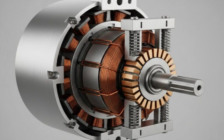
- Physical pieces of a split ring commutator:
- Two (or more) copper segments: curved, mounted on the shaft, insulated from each other.
- Insulation: often mica or similar material keeping segments electrically separate.
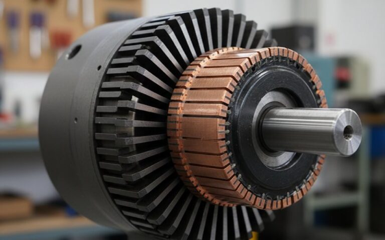
- Brushes: usually carbon blocks that stay still and press lightly on the rotating segments.
- Rotor shaft / armature: the commutator is fixed to it, so they spin together as one piece.
- Two (or more) copper segments: curved, mounted on the shaft, insulated from each other.
3. Why is a split ring commutator needed in a DC motor?
Let’s go back to the “vibrating instead of spinning” problem. The trick is simple but clever:
Whenever the coil passes the vertical position (every 180°), you reverse the current through it.
That way, even though the coil’s physical sides swap positions, the combination of current direction and magnetic field is adjusted so the force on each side still pushes in the same rotational direction. The torque never flips sign, so the motor keeps turning smoothly.
You’ll often see this summarised in revision notes as:
“The split ring commutator reverses the direction of current in the coil every half rotation so that the coil continues to rotate in the same direction.”
- In a DC motor, the split ring commutator:
- Reverses current every half turn, keeping torque pointing the same way.
- Prevents stalling when the coil reaches its “neutral” vertical position.
- Smooths rotation, reducing the back-and-forth jerking that would otherwise happen.
- Connects the rotating coil to the stationary power supply through the brushes.
- Reverses current every half turn, keeping torque pointing the same way.
4. Why is a split ring commutator needed in a DC generator?
Now flip the story. Instead of sending current into the coil to make it spin, we mechanically spin the coil (using a turbine, hand crank, etc.) in a magnetic field and take current out. That’s a generator.
Here’s the catch: as the coil spins, the induced electromotive force (EMF) naturally oscillates—it changes direction every half turn, like a sine wave. That means:
- The raw EMF in the coil is AC (alternating current), no matter what you do.
- But many applications (batteries, old-school DC systems, some control circuits) specifically want unidirectional DC output.
The split ring commutator solves this by mechanically rectifying the output:
- Just as the EMF in the coil is about to reverse, the ring segments swap which brush they touch.
- The coil’s polarity flips relative to the brushes at the same time as the induced EMF flips.
- The combination means the output at the brushes always has the same polarity (still wiggly in size, but not in sign).
So in a DC generator, the split ring commutator is needed not for torque direction, but to turn an AC-in-the-coil situation into DC at the terminals.
- In a DC generator, the split ring commutator:
- Swaps the connections of the coil to the external circuit every half turn.
- Flips the coil polarity relative to the terminals exactly when the induced EMF changes sign.
- Produces pulsating DC instead of AC at the output.
- Acts as a mechanical rectifier, performing the same logical job as a diode bridge in modern electronics.
- Swaps the connections of the coil to the external circuit every half turn.
5. Split ring vs slip ring: why not just use a continuous ring?
Here’s where many students get confused: there are split rings and slip rings, and they are not the same thing.
- Slip rings are complete, continuous rings. They simply carry current or signals across a rotating interface without changing polarity. They’re common in AC motors, wind turbines, rotating radars, etc.
- Split rings are broken into segments (typically two) and are used when you want polarity reversal—like in DC motors and generators.
Quick comparison table
| Feature | Split Ring Commutator | Slip Ring |
| Physical shape | Ring split into two or more insulated segments | Continuous unbroken ring(s) |
| Used mainly in | DC motors and DC generators | AC machines, rotating joints, wind turbines |
| Main purpose | Reverse polarity every half turn | Provide continuous connection while rotating |
| Output type (generator context) | Converts induced AC to pulsating DC | Leaves output as AC |
| Torque effect (motor context) | Keeps torque in one direction | Would cause torque to reverse every half turn |
| Typical number of rings | Often 2 (for single-coil DC motor) | 1 or several, depending on phases |
| Gap / insulation | Has gaps between segments | No gap; rings are continuous |
- Memory hack:
- “Split = Switch” – split ring switches the connections.
- “Slip = Slide” – slip ring just lets current slide from stationary to rotating parts with no trickery.
- “Split = Switch” – split ring switches the connections.
6. What exactly happens without a split ring commutator?
Let’s walk through two “no commutator” thought experiments.
In a motor:
- Start with a loop in a magnetic field, powered by DC.
- For the first half turn, everything is fine—the forces on each side of the coil produce a torque in one direction.
- After half a rotation, the coil is upside down. The direction of the forces, relative to its position, has now reversed.
- Now torque tries to spin it back the way it came.
End result: unless there’s some tricky mechanical asymmetry, friction and inertia make the rotor oscillate around the neutral position. It doesn’t become a useful motor.
In a generator:
- You mechanically rotate the coil.
- The induced EMF in the coil alternates.
- With plain slip rings, external terminals see that AC directly.
- If your load expects DC (e.g., charging a battery), this is a problem.
End result: without the split ring, the generator becomes an AC generator; to get DC you’d have to add an electronic rectifier later.
- Summary of “no split ring” consequences:
- DC motor: coil rocks or stalls; no sustained one-way rotation.
- DC generator: output is AC instead of DC; not suitable for direct DC loads without extra electronics.
- DC motor: coil rocks or stalls; no sustained one-way rotation.
7. Inside the action: how the split ring and brushes dance together
The magic is all about timing. As the rotor spins, each coil side moves from “pushed up” to “pushed down” relative to the magnetic field. At the exact moment when the torque would change sign, the commutator steps in.
Picture this:
- During the first half turn, segment A of the commutator is touching brush 1, and segment B touches brush 2.
- When the coil reaches the vertical position, the segments slide under the brushes and swap contacts: segment A now connects to brush 2, and segment B to brush 1.
- The coil ends swap which external terminal they’re tied to.
- In a motor, that reverses current. In a generator, it flips which side of the coil you call “positive,” so the external polarity stays consistent.
This is why you’ll often see the split ring described as a rotary switch that reverses current every 180°.
- Brushes + split ring: how they share the workload
- The commutator segments handle the time-critical job of swapping connections.
- The brushes provide a (relatively) stable contact to the outside world and also take the mechanical wear instead of the more expensive rotor parts.
- The commutator segments handle the time-critical job of swapping connections.
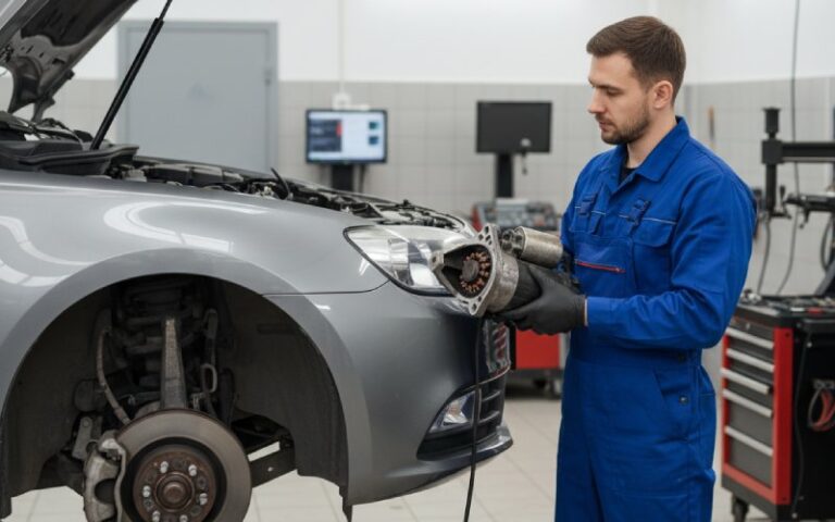
8. Real-world issues: wear, sparking, and maintenance
All this clever switching comes at a cost: mechanical wear and electrical stress.
Because the brushes constantly rub on the moving copper segments:
- Surfaces wear down over time.
- Tiny gaps and imperfections can cause arcing (sparks).
- Dust from worn brushes can accumulate and cause tracking or shorts.
Textbook revision notes often emphasise that maintaining the commutator and brushes is critical for keeping DC motors efficient and reliable—cleaning, smoothing, and occasionally replacing parts.
- Common commutator problems in the field:
- Brush wear – brushes get shorter and need replacement.
- Pitting / rough segments – cause increased sparking and noise.
- Carbon dust build-up – can create unintended conductive paths.
- Overheating – from excessive current or poor contact, leading to discoloration and damage.
- Brush wear – brushes get shorter and need replacement.
9. Modern twist: if split rings are “old school”, why still learn them?
Modern motors increasingly use brushless DC (BLDC) or synchronous AC designs with electronic commutation—transistors and control chips that do the polarity-flipping without physical brushes or copper segments. These avoid commutator wear and can be more efficient and quiet.
But split ring commutators still matter because:
- They’re conceptually simple and perfect for teaching the essentials of electromagnetic torque and energy conversion.
- Many small, low-cost tools and toys still use brushed DC motors because they’re cheap, robust, and easy to power from batteries.
- Understanding mechanical commutation helps you appreciate what the electronics in brushless motors are imitating.
- Where you’re likely to meet split ring commutators today:
- Toy motors, hobby kits, and school lab motors.
- Low-cost DC fans, pumps, and power tools.
- Automotive starter motors and older vehicle systems.
- Educational DC generators in labs and demos.
- Toy motors, hobby kits, and school lab motors.
10. Quick FAQ-style recap
If you remember nothing else, remember this:
A split ring commutator is needed whenever you want a spinning coil in a magnetic field to behave “as if” the current never reverses direction at the terminals—even though the geometry does.
It’s the tiny mechanical trick that keeps your motor spinning smoothly and your generator delivering DC.
Q: What is the single main job of a split ring commutator in a DC motor?
A: To reverse the current in the armature every half turn so torque always acts in the same rotational direction.
Q: What is its main job in a DC generator?
A: To flip the coil connections so that the output at the brushes always has the same polarity—turning AC inside the coil into DC outside.
Q: How is it different from a slip ring?
A: A slip ring is continuous and just passes current through; a split ring is segmented and deliberately reverses connections.
Q: Can we avoid using split rings in modern designs?
A: Yes—by using brushless motors and electronic commutation—but the underlying physics concept is the same.