Why Are Commutators Segmented Instead of Solid Rings?
If you work with DC motors, universal motors, or generators long enough, this question eventually appears on a drawing review call:
“Why don’t we just use a solid copper ring here? Wouldn’t that be simpler?”
Short answer: a solid ring stops being a commutator. It becomes a slip ring. And your machine stops behaving like the DC machine you specced.
The longer answer is where things get interesting for engineers, and for purchasing.
Table of Contents
1. What a “solid commutator” would actually do
Imagine you replace the segmented commutator with one continuous copper ring, still pressing carbon brushes on it.
Now you have:
- One ring
- One continuous contact surface
- No discrete bars, no mica insulation between them
Electrically, that’s a slip ring arrangement. Power transfer is still possible, sure, but you’ve removed the core function of a DC commutator: switching current between individual armature coils so the torque stays roughly unidirectional.
So with a solid ring:
- No segment-to-segment switching
- No controlled commutation zone
- No way to map individual coils to specific angular positions
You can still build a machine around that, of course. It just isn’t a DC commutated machine anymore.
For a buyer: a “solid commutator” on a DC motor drawing is really a red flag. Either the term is being misused, or the design isn’t what the spec claims.
2. Electrical reasons the commutator must be segmented
2.1 Current reversal has to be local, not global
In a practical DC machine, each armature coil terminates on a dedicated pair of commutator segments. As the rotor turns, the brush spans two adjacent segments for a brief angle. During that short time, the coil is effectively shorted and its current reverses.
That only works because:
- Each segment is electrically isolated from the next by mica or another insulation
- The brush only connects a few segments at once
With a solid ring, there is nothing to switch. Every coil end tied to the same copper body would just sit at the same potential. No commutation. No way to reverse individual coil currents.
So segmentation is not a feature. It is the whole method.
2.2 Torque ripple and “too few segments” reality
Why not just use a tiny number of big segments? Textbooks show the “two segment” picture. Real machines almost never do that.
More segments mean:
- At any rotor angle, more coils are near their ideal torque position
- The torque ripple is reduced
- The machine is easier to start and runs more smoothly
Engineers on design forums often summarise it very bluntly: adding more segments and coils keeps at least one coil in a good torque position at all times.
But there’s a trade:
- More segments → more bars to manufacture, more joints, more inspection points
- Fewer segments → cheaper part, but higher ripple torque, rougher running, higher brush stress
For an industrial buyer, this is where cheap commutators start to get expensive again in the field.
2.3 Managing inductive stress and sparking
Each coil carries current and has inductance. During commutation you are forcing that coil’s current to change sign in a very short time window. That means high di/dt, which wants to create voltage spikes and brush sparking.
Segmented design helps you manage this:
- Each commutating coil is tied to a small part of the circumference
- The brush shorts only a couple of segments at once
- The voltage per segment is limited, so the arc energy is limited
Educational material often points out that segmented commutators allow more precise control over commutation and reduce the risk of sparking when designed correctly.
With a solid ring, there is no per-segment voltage, because there are no segments. Every coil end is effectively on the same electrode. You lose the whole control mechanism.

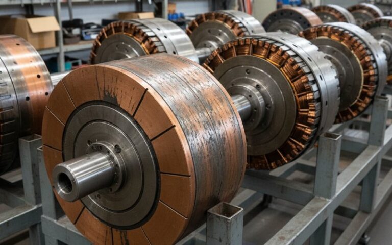
3. Mechanical and thermal reasons for segmentation
Even if you ignored the physics and tried to force a “solid commutator”, the mechanics would fight you.
3.1 Copper bars plus mica are a stress relief system
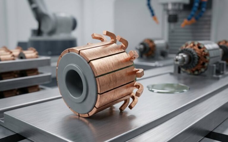
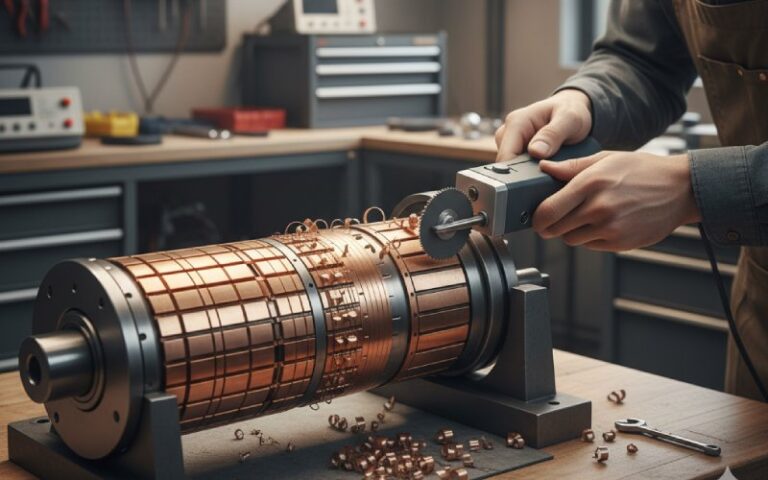
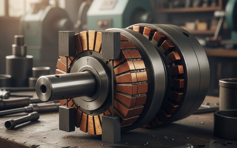
Practical commutators are built as:
- Many wedge-shaped copper bars
- Radially locked in a hub
- Each bar separated by segment mica or a similar insulator
This construction:
- Electrically isolates each bar
- Allows the copper to expand and contract with temperature
- Lets the stack behave like a flexible ring instead of a rigid band
A solid thick copper ring, shrunk onto a steel hub, would see:
- Differential expansion between copper and steel
- High circumferential stress
- Out-of-round issues as it heats and cools
Which you will eventually meet as:
- Uneven brush loading
- Localised wear
- Noise, vibration, brush chatter
The segmented construction is partly about electricity, partly about letting the mechanics breathe.
3.2 Slots, contamination, and wear control
Real commutators live in dust, oil, and carbon brush debris. Segment slots, undercut depth, and slot shape all affect how that contamination behaves.
Design references talk about V-slots versus U-slots:
- V-slots: collect less dirt, better in slow or dirty environments
- U-slots: allow the bar to wear deeper before undercutting is needed
You cannot tune that behaviour with a featureless solid ring. Segments and their slots are part of the tribology package: current density, brush grade, surface speed, environment.
3.3 Repairability and “refilling”
On larger industrial machines, commutators are built to be repairable:
- Individual segments can be removed
- Insulation can be replaced
- The stack can be “refilled” instead of scrapping the whole rotor
This matters for:
- Mining drives
- Steel mill motors
- Large DC generators
If you commit to a solid ring concept, you also commit to full-rotor replacement on any serious damage.
Purchasing feels that as:
- Higher spares cost
- Longer outages (rotor replacement vs commutator rebuild)
- More logistics complexity on large equipment
Segmentation is one of the reasons big DC machines are still serviceable after decades.
4. Segmented commutator vs solid ring vs slip ring
To line things up for both engineers and buyers, here is a compact comparison. The “solid commutator” column is really a thought experiment — in practice it behaves like a slip ring for most of these points.
| Feature / concern | Segmented commutator | Hypothetical solid copper ring | Slip ring assembly |
|---|---|---|---|
| Electrical role | Switches DC between coils to maintain torque | No switching; all coil ends commoned | Transfers power/signals without switching |
| Supports DC motor/generator action | Yes | No | No |
| Torque ripple (with proper design) | Low to moderate; configurable by segment count | High / poorly defined | Depends on machine type, not used for DC commutation |
| Voltage per contact area | Limited by per-segment voltage | Entire armature voltage on one body | Entire phase or circuit voltage on one ring |
| Sparking behaviour | Can be controlled via segment design, brush grade | Difficult to control; switching has no structure | Typically low, because no commutation switching |
| Mechanical stress handling | Segments plus mica act as stress relief | Higher hoop stress, risk of distortion | Similar hoop issues, but usually smaller diameter |
| Maintenance options | Resurfacing, undercutting, segment replacement | Whole ring/rotor replacement | Resurfacing or ring replacement |
| Typical applications | DC motors, universal motors, DC generators | Almost none in practice | AC generators, rotating sensors, wind turbines |
| Suitability for high power DC machines | Proven, mature, serviceable | Not used | Not applicable |
If you are reading this as a buyer: the column that actually exists in your RFQs is the first one.
5. Design choices that make segmentation work (or not)
Once you accept that “segmented” is not optional, the real engineering decisions begin.
5.1 Number of segments
More segments:
- Lower voltage per bar
- Shorter commutation per bar
- Smoother torque and lower ripple
- Smaller current step per segment
But also:
- More complex manufacturing
- More joints to inspect
- Tighter tolerance on bar width and gap
Too few segments, on the other hand:
- Increase bar voltage
- Increase brush sparking risk
- Can limit maximum speed under load
A design team typically balances segment count against rated voltage, speed, allowable ripple, and cost. Reference material on DC machines makes the same point: extra coils and segments are added specifically to smooth the pulsating output.
5.2 Segment geometry and connection style
Not all segmented commutators look the same inside.
Common options:
- Conventional (slotted) commutators: each segment has slits to hold the magnet wire, then the wire is fused; these are very robust and popular for high-vibration or high-RPM uses.
- Tang / hook type: wires are bent around tangs or hooks on the riser, with different assembly advantages.
- Groove or shell designs: for larger machines, focused on mechanical strength and cooling.
Geometry choices affect:
- Vibration resistance
- Assembly cost
- Ease of rework
- How compact the motor can be for a given rating
Again, something a “solid ring” simply cannot do: there is nowhere to land and secure the winding ends.
5.3 Insulation system
The unsung hero here is mica and related materials.
Industrial commutator guides note that:
- Copper bars are separated from each other and from the hub by mica
- Mica stays stable under the pressure and temperature of operation
- The combination of copper + mica segments gives both insulation and mechanical stability
For purchasing, “mica grade” is often just a line item. For the engineer, it has consequences:
- Temperature rating
- Moisture resistance
- Machinability and undercut behaviour
- Long-term dimensional stability
If the insulation creeps or cracks, your segment stack loses alignment or tracking. At that point, solid ring or segmented, everyone is unhappy.
5.4 Brush system pairing
Segmentation and brush system are a matched set.
Brush width, brush material, and spring pressure are chosen so that:
- The brush spans around 2–3 segments
- The commutating coil is properly shorted in the commutation zone
- Current density stays within allowable limits at rated load
A change in segment width or gap that looks minor on a drawing can move you into a region where:
- The brush intermittently bridges too many segments
- Commutation is extended in angle
- Sparking increases
So when a supplier proposes a “simplified” commutator design, make sure brush geometry is being rechecked alongside.
6. What this means for sourcing and specification
Engineers usually ask, “How many segments do we really need?”
Purchasing usually asks, “What levers do I have on cost without risking field failures?”
Segmentation is one of those areas where a bit of structure in the specification can prevent bad surprises.
6.1 Practical checklist for buyers
When you send a commutator RFQ, consider making these points explicit:
- Type of machine and duty
- DC motor, universal motor, generator
- Duty cycle, start/stop frequency, reversal or not
- Electrical data
- Rated voltage and speed
- Target ripple torque range (if known)
- Expected overloads, short-term and continuous
- Mechanical constraints
- Maximum outer diameter and stack length
- Allowable runout and out-of-round
- Vibration environment
- Segmentation details
- Target number of segments (or at least a range)
- Preferred bar material
- Slot style (U/V etc.) if your application is sensitive to contamination
- Service expectations
- Whether segment replacement / refilling must be possible
- Minimum expected resurfacing allowance
Suppliers that specialise in commutators often publish their own design guidance and standard series. They will happily tune segment count, bar shape, and mica system to your duty, as long as they have enough detail.
7. FAQs: segmented commutators vs solid rings
Q1. Can we reduce the number of segments to cut cost?
Yes, but with limits.
Reducing segment count can:
Lower manufacturing and inspection cost
Reduce complexity of winding terminations
But you pay in:
Higher voltage per segment
Rougher torque
Higher brush stress and potential sparking
For most industrial DC machines, segment count is already near the practical minimum dictated by voltage and ripple requirements. Treat any large reduction proposal with caution.
Q2. Why can’t we just use slip rings instead of a commutator?
Slip rings are continuous rings used to transfer power or signals to a rotating part without switching. They’re great in AC alternators, wind turbines, rotating sensors, and so on.
A DC commutator, on the other hand, must:
Reverse current in individual coils at specific rotor angles
Maintain roughly constant torque direction
Slip rings cannot do that on their own. You’d need electronics to replace the commutator’s function, at which point you’re designing a completely different drive system.
Q3. Why is mica almost always mentioned with commutator segments?
Because the copper alone is useless without reliable insulation.
Mica:
Electrically isolates the bars from each other and from the hub
Survives the temperatures and mechanical stress of operation
Holds up during machining and undercutting
If the insulation system is poor, the commutator will suffer bar-to-bar faults, tracking, or movement, regardless of how beautiful the copper looks on day one.
Q4. Does more segments always mean longer brush life?
Not automatically.
More segments generally mean:
Lower bar voltage
Smoother torque
Smaller current step during commutation
All of which can reduce brush wear.
But if:
Brush grade is wrong
Brush pressure is mis-set
Surface speed is too high for the chosen system
Then brushes will still wear fast, even on a very fine segmented commutator. Brush and commutator are a paired design, not independent.
Q5. For a low-cost appliance motor, do we really care about segment repairability?
Usually not.
Small universal motors in tools and appliances typically use:
Molded, non-refillable commutators
Crimped construction that is not designed for rebuild
In those markets:
The motor is a throwaway item
The commutator is optimised for production cost and adequate life, not serviceability
For large industrial drives, the story flips completely. Refillable, segment-replaceable designs are standard there.
Q6. What drawing data helps a commutator supplier quote accurately?
Very practical items:
Detailed segment count and indexing
Insulation requirements (material family, temperature class)
Max allowable runout, bar height tolerance, and gap tolerance
Surface finish requirements
Required high-speed test or balancing procedure
The more of that you specify up front, the fewer “interpretations” come back later in the process.
8. Key takeaways for engineers and buyers
A commutator is segmented because it has to be:
- Electrically, to give you controlled current reversal, manageable voltage per segment, and acceptable torque ripple.
- Mechanically, to survive thermal expansion, contamination, and decades of brush contact without turning into an oval.
- Commercially, so that large machines can be serviced by replacing segments instead of entire rotors, keeping lifecycle cost under control.
So when someone asks, “Why can’t we use a solid ring?”, the real answer is:
Because then it isn’t a commutator anymore. It’s just copper. And all the useful behaviour lives in the segments.