What Is a Split Ring Commutator?
You already know the textbook answer:
A split ring commutator is a rotating copper ring, cut into insulated segments, that reverses current in a DC armature every half turn so torque stays in one direction.
Good. Let’s not stay there.
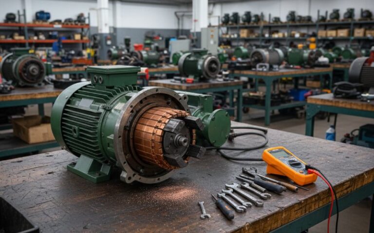
This article looks at the split ring commutator the way a motor or generator team actually meets it: as a noisy, wearing, copper-and-mica part that quietly decides your warranty costs, brush life, and efficiency.
Table of Contents
1. Quick refresher (then we move on)
In a brushed DC motor or DC generator, the split ring commutator:
- Sits on the shaft, fixed to the armature
- Connects each armature coil to a pair of copper segments
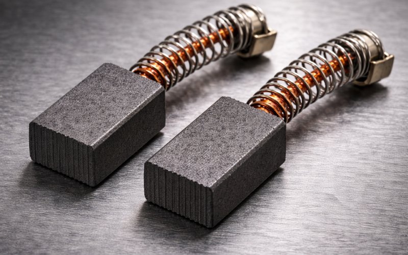
- Works with carbon/graphite brushes that span multiple segments
- Swaps which segment is under which brush every half turn, so the current in the active coils flips and the torque on the rotor keeps pointing roughly the same way
Nothing new there. The interesting part is how that rotating copper cylinder is built and tuned so it can do this all day at thousands of RPM without turning into an arc furnace.
2. What a split ring commutator is actually made of
Ignore the neat school diagrams for a moment and think in stack-up terms.
2.1 Core construction
Most industrial commutators for brushed DC machines share a common recipe:
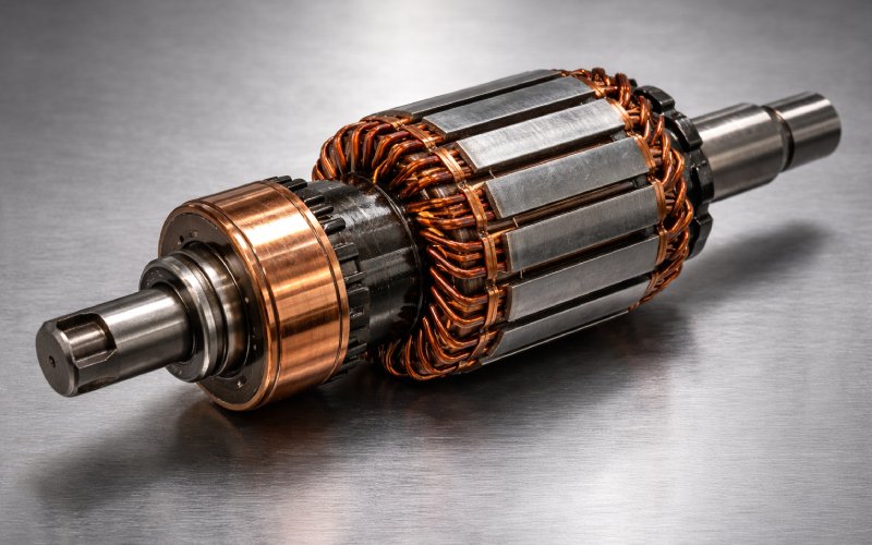
- Hard-drawn copper segments (bars)
- Arranged around the shaft like slices of an orange
- Each bar is mechanically keyed to a hub or shell
- Mica insulation between segments
- Sheet mica in the range of about 0.7–2 mm thick between bars
- High dielectric strength, high temperature stability
- Mica undercut below the surface
- The mica between segments is cut back ~1 mm (or around 1/16″ for medium bars) from the running surface so the brushes ride on copper, not mica
- Steel or plastic shell / hub
- Holds everything concentric and transmits torque
- Risers / tangs
- Slots or lugs where coil ends are soldered
So “split ring” is a bit too friendly. It’s really a laminated copper cylinder with precision mica gaps and a very fussy surface finish requirement.
2.2 Geometry that usually gets decided late (but shouldn’t)
Design guides often hide the most painful choices in a couple of lines:
- Commutator diameter typically 60–80% of armature diameter to keep peripheral speed under about 15 m/s for standard carbon brushes
- Segment pitch should not go below 4 mm for mechanical robustness in many machine designs
- Brush width often spans 2–3 segments, covering roughly 8–12% of the circumference in larger machines
Those numbers look harmless. Until you’re chasing arc marks at the brush face and find out the brush is just wide enough to bring a “bad” coil into the commutation zone.
3. Key design parameters and what they really change
Here’s a compact view you can drop into a design review. Values are indicative, not rules.
| Design lever | Typical range / choice (industrial DC) | What it really shifts | Quiet notes from the shop floor |
|---|---|---|---|
| Commutator diameter / armature diameter | 0.6–0.8 × armature diameter | Surface speed, brush wear, size | Too small → high current density at surface; too big → harder to keep round, more copper cost. |
| Segment pitch | ≥ 4 mm | Mechanical strength, minimum brush thickness | Very fine pitch looks great on paper, then chips during manufacturing or repair. |
| Number of segments | = number of active coils in classic designs | Ripple in torque / voltage, fault isolation | More segments = smoother torque, more solder joints to worry about. |
| Mica thickness | Around 0.8 mm between bars | Dielectric strength, heat path | Thicker mica is not always safer; it’s also more thermal resistance and more undercutting work. |
| Mica undercut depth | About 1 mm below copper surface for many bars | Brush noise, arcing, film stability | High mica (undercut too shallow or worn copper) is a classic cause of brush chatter and streaking. |
| Brush material | Normal carbon / soft graphite / electro-graphite / metal-graphite | Voltage drop, friction, film formation | Commutator design and brush grade are a pair; changing one without the other usually shows up as sparks. |
| Max peripheral speed | Often kept ≤ 15 m/s for standard carbon brushes | Mechanical stress, temperature, film stability | Pushing speed means stricter roundness tolerance and better balancing; the copper cylinder becomes a flywheel. |
If you only touch three levers early: pick the diameter, segment pitch, and brush grade together. The rest follows more naturally.
4. Split ring vs. slip ring: not just “DC vs AC”
You’ve heard the one-liner:
- Slip ring – continuous ring, continuous current direction (typical in AC machines)
- Split ring commutator – ring cut into segments, used to reverse current in DC coils
At B2B level the real gap is here:
- Waveform shaping
- In a DC generator, the split ring commutator literally rectifies the induced AC into a pulsed DC output.
- In a DC motor, it shapes the current distribution so the torque is mostly unidirectional.
- Contact conditions
- Slip rings can often tolerate modest pitting and still pass AC power.
- Split ring commutators are much more sensitive; sparking changes the commutation wave form and eats both copper and brushes.
- Service model
- Slip rings: typically “clean, inspect, maybe regrind”.
- Split ring commutators: add mica undercut, bar tightness checks, and sometimes complete re-segmenting.
So if someone suggests “we could just use slip rings here”, the hidden question is: who is going to flip the current? Either electronics will do it, or you pay that complexity in copper and mica.
5. Where split ring commutators still make sense
Even with brushless and electronic commutation everywhere, split ring commutators are not going away. They sit where the combination of simple DC supply + good torque control + acceptable maintenance beats added electronics:
- Small and medium industrial DC drives and hoists
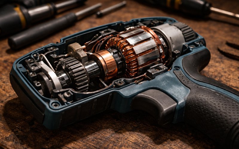
- Power tools and appliances that still rely on brushed DC motors
- Low-voltage DC generators, test rigs, lab machines
- Legacy systems where the mechanical interface and duty cycle are already proven
From a sourcing side, that means:
- Stable, mature technology
- But also an ecosystem of repair shops, commutator turners, mica undercut services
Which is good news if you’re responsible for total lifetime cost instead of just BOM.
6. Failure signatures that point straight to the commutator
Textbooks usually stop at “sparking is bad”. Real machines are more specific. A few patterns:
6.1 Heavy sparking at one brush arm
Symptoms:
- Intense sparking at one brush set, others look normal
- Local blue or black discoloration on a group of bars
- Possible humming or vibration at certain loads
Likely culprits:
- Commutator out of round in that zone → brush bounce
- Local high mica between specific bars
- Loose or lifted bars in that region
Action:
- Check roundness (dial gauge or at least feel for brush movement)
- Inspect bar tightness and undercut depth
- If the pattern follows one brush, also check brush holder alignment and pressure.
6.2 Uniform pale streaks, noisy brushes
Symptoms:
- Brush noise (“chatter”) grows over time
- Streaky, pale commutator surface rather than an even brown film
- Brushes wearing faster than expected
Often connected to:
- Mica no longer undercut enough (copper wore faster than mica)
- Film never stabilises because the brush rides partly on mica ridges
Action:
- Re-undercut mica to the specified depth
- Re-seat brushes and let a new film form under controlled load.
6.3 Dark burnt bars and persistent arcing
Symptoms:
- One or more bars are darker and rough
- Arcing even at light load
- Sometimes associated with a single open or shorted armature coil
This is where the split ring nature matters: each bar is tied to a coil. A failed coil disturbs the current distribution just as that bar passes under the brush, and the commutation event becomes a small welding test.
Action:
- Insulation tests / bar-to-bar tests
- Decide between armature rewind or full commutator replacement.
7. Specifying a split ring commutator to a supplier
Here’s the part many teams under-specify. Sending only “DC motor, 5 kW, 3000 rpm” is asking for trouble.
When you brief a commutator manufacturer, you want at least:
- Electrical data
- Rated voltage and current
- Winding scheme (lap / wave) and number of active coils
- Max allowed voltage between adjacent bars (important for number of segments)
- Mechanical data
- Armature diameter and length
- Target commutator diameter and length (or the constraints they must fit inside)
- Max peripheral speed at rated speed
- Shaft details and keying method
- Brush system info
- Brush material family (carbon / graphite / metal-graphite)
- Brush dimensions and number per arm
- Brush holder style and pressure range
- Environment
- Ambient temperature range
- Presence of oil mist, dust, corrosive gases, moisture
- Cooling arrangement (self-ventilated, forced air, enclosed)
- Maintenance model
- Is the commutator expected to be turned / reground in service?
- Is mica undercutting handled in-house or outsourced?
- Expected brush life hours, overhaul intervals, and access constraints
Getting this into the RFQ saves you from the classic “works in the lab, dies at the customer site” problem.
8. Split ring commutator vs. “just go brushless”
Someone in every project meeting says: why not go brushless and get rid of commutators completely?
Good question. Rough rule of thumb:
- If you already have a DC machine platform, established commutator supply, and modest dynamic performance needs → split ring commutator still looks attractive on cost.
- If you need tight speed control, high power density, or harsh environments → brushless design plus electronics often wins.
From an OEM point of view, it’s not about fashion. It’s about where complexity lives: in copper and mica, or in silicon and firmware.
Split ring commutators are what you choose when you want complexity to stay in the mechanical domain, where repair shops still know what to do.
9. FAQ: split ring commutators for B2B buyers and designers
9.1 Is a split ring commutator always made of copper and mica?
Almost always in industrial brushed DC machines:
Segments: hard-drawn copper (sometimes with specific alloy tweaks)
Insulation: mica or micanite sheets between segments, plus supporting resins
Other exotic systems exist, but if you’re buying in volume, you will almost certainly be offered copper + mica.
9.2 How many segments should my split ring commutator have?
There is no fixed “good” number. It is usually equal to the number of armature coils in classical designs. More segments:
Reduce torque ripple / voltage ripple
Improve commutation smoothness
Increase manufacturing complexity and the number of possible fault points
For a new design, you normally start from the winding layout and acceptable volts per segment, then back-calculate the segment count.
9.3 Can an old commutator be restored, or should it always be replaced?
Typical options, in rising cost:
Clean and burnish – for mild film issues and light scoring
Turn and undercut – small diameter reduction on a lathe, then re-undercut the mica
Full replacement – for loose bars, deep burning, or severe eccentricity
The decision usually comes down to remaining bar height and whether any coils or risers are damaged.
9.4 Why does brush grade matter so much for a split ring commutator?
Because the commutator is not just copper; it’s copper plus the thin graphite / copper oxide film from the brushes. That film:
Lubricates the interface
Limits sparking
Sets contact resistance
Different brush grades create and maintain that film differently. So a commutator that runs quietly with one carbon grade can become noisy and hot with another.
9.5 What is “high mica” and why do service reports complain about it?
“High mica” means the mica between commutator bars is no longer recessed below the copper surface. Either:
The copper has worn down
The mica was not undercut enough after resurfacing
When mica reaches brush level, brushes ride up on the hard insulating ridges, contact worsens, noise increases, and sparking appears. The fix is simple but tedious: re-undercut the mica to the specified depth and clean the slots.
9.6 Does a split ring commutator work differently in a generator than in a motor?
The physical hardware is almost the same. What changes is the viewpoint:
In a motor, the commutator is steering current into coils so the torque direction stays roughly constant.
In a generator, you can think of it as rectifying the induced AC into a pulsating DC output.
Either way, the commutator is switching current at the same mechanical angle positions. The rest is naming.
9.7 One last practical question: if I’m auditing a supplier, what should I actually look at on the commutator?
Quick checks that say a lot:
Consistent mica undercut, no high spots
Even brown running film, no streaks or heavy local burning
Bar edges lightly chamfered, not sharp
No visible looseness or movement of segments
Dimensional control on diameter and runout against spec
If those items are under control, the rest of the quality system is usually in decent shape.