What Is a Slip Ring Commutator? A Practical Guide for Industrial Buyers
In actual projects, that phrase usually means one of three things: a continuous slip ring, a segmented commutator, or a rotary electrical contact assembly that has not been specified clearly yet. A slip ring keeps electrical continuity while the part rotates. A commutator does something else. It switches the rotor connection as the machine turns, so current reversal happens at the required position. Same family of components. Not the same function.
That distinction matters earlier than most RFQs suggest. If the function is misread at the quotation stage, the failure usually appears later as arcing, unstable signal, abnormal brush dust, edge burning, rapid wear, or a ring surface that never settles into stable operation. We see that pattern often enough. The name looks close. The duty is not.
Table of Contents
Slip Ring vs Commutator: What Is the Difference?
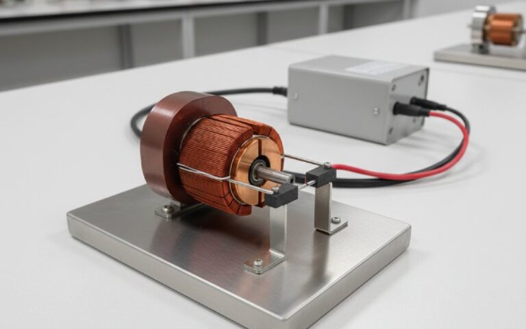
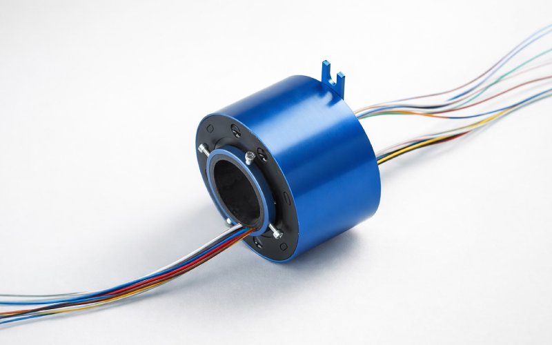
A slip ring is built for continuous electrical transfer between stationary and rotating parts. The ring surface is continuous. The brush stays in contact and the circuit stays continuous through rotation. This is the normal choice when the job is power transfer, excitation current, control signal, sensor signal, or a mixed power-and-signal package.
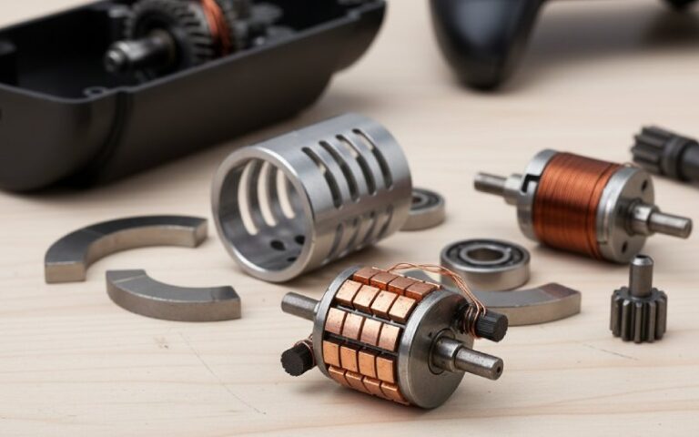
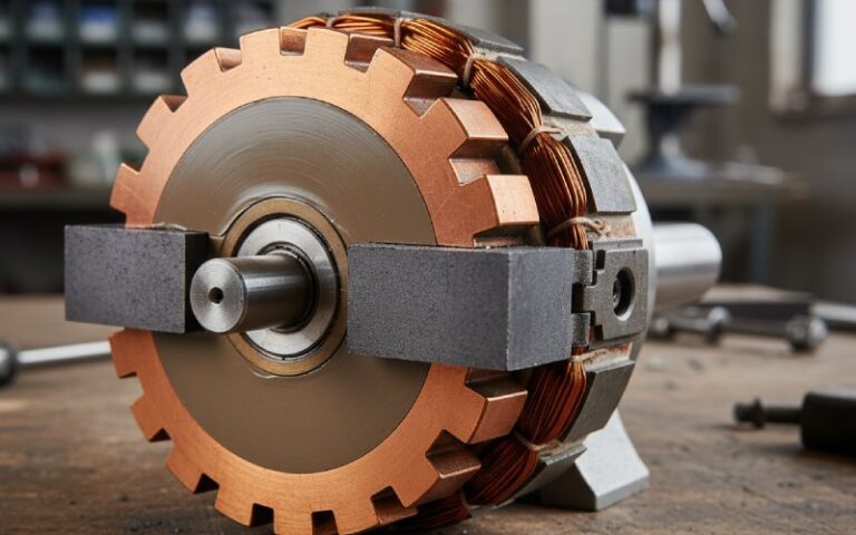
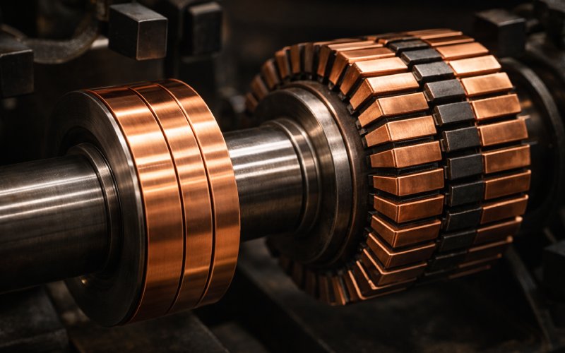
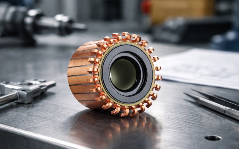
A commutator is built for mechanical switching. Its copper surface is segmented, not continuous. As the armature rotates, the brush moves from one segment to the next, and the current in the relevant coil is reversed at the correct point in rotation. That switching action is what allows a DC machine to keep torque in one direction or deliver one-direction output from the terminals.
So when someone asks, “What is a slip ring commutator?” the shortest correct answer is this:
In most B2B inquiries, a slip ring commutator is not a precise engineering term. It usually refers to a brush-based rotary electrical contact system, but the actual part may need to be defined as either a slip ring or a commutator before production can be quoted correctly.
How We Read This Term in Factory Work
We use one question first:
Does the circuit need continuous transfer, or timed switching?
If it needs continuous transfer during rotation, we move toward a slip ring solution. If it needs rotor-side switching during rotation, we move toward a commutator solution.
That sounds simple. It usually is not.
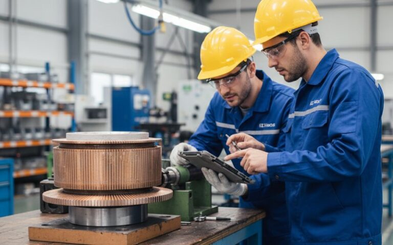
Many inquiries arrive with only a motor photo, a worn sample, or one line like “need slip ring commutator for generator.” That is not enough to lock the design. We still need speed, current per path, voltage, insulation spacing, duty cycle, space limit, atmosphere, and whether power and signal must share the same assembly. Once those are clear, the right architecture becomes obvious. Before that, it does not.
Slip Ring Commutator Selection Table
| Inquiry term | What it usually means in practice | Main electrical behavior | Typical applications | What we verify before quoting |
|---|---|---|---|---|
| Slip ring | Continuous ring with brush contact | Maintains continuous connection during rotation | Generators, rotary tables, packaging equipment, winding systems, test rigs | Current per circuit, signal type, speed, noise limit, environment |
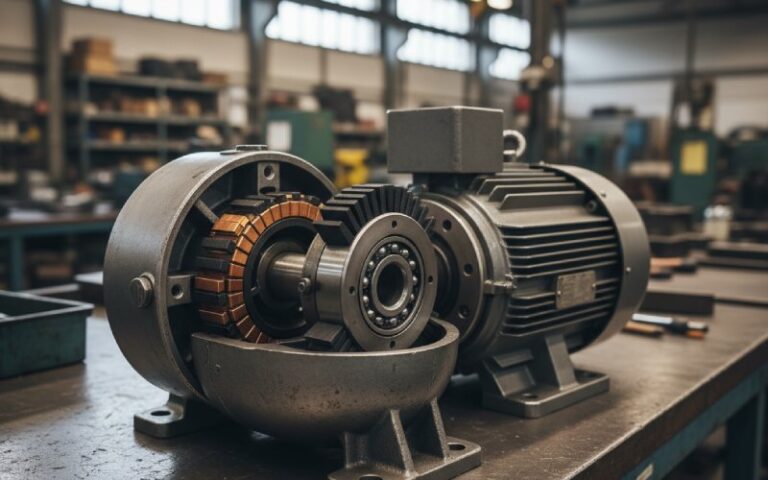
| Commutator | Segmented copper switching element | Reverses current in the rotating winding during rotation | DC motors, DC generators, automotive motors, power tools, appliances | Segment count, OD/ID, riser or hook type, mica condition, brush system |
| Slip ring commutator | Search term or incomplete RFQ term | Could mean either system above | Early-stage sourcing, replacement requests, sample-based inquiries | First define function, then size, then materials, then brush interface |
How a Slip Ring Actually Fails in Service
A slip ring does not fail because the drawing was ugly. It fails because the contact system was asked to do more than the specification admitted.
For low-current or mixed-signal designs, the first thing we watch is contact resistance stability. Not just nominal resistance. Stability. A rotary contact can pass power and still perform badly on analog or data channels if resistance fluctuation, shielding, impedance mismatch, or crosstalk were ignored in the early design stage. That becomes more obvious when multiple power, signal, and data paths are forced into a compact package.
Then there is dust. Then vibration. Then low humidity. Then brush pressure that looked acceptable on paper but not on the actual ring surface. Small errors pile up at the interface. They do not stay small for long. Surface contamination raises friction. Weak spring pressure breaks contact stability. Abrasive debris and poor film condition push the ring toward wear, noise, or arcing.
That is why we do not like vague requests such as “same as old part.” The old part may have been running badly for months before it was removed.
How a Commutator Fails in Service
With a commutator, the problem is not only conduction. It is commutation quality.
If the short-circuited coil does not complete current reversal while passing under the brush, sparking starts. When armature reaction shifts the magnetic neutral axis and the brush position no longer matches the true commutation zone, the commutator can move from acceptable to destructive fairly quickly. The machine may still run. The surface will tell a different story. Edge burning, bar marking, copper drag, chatter, and heavy dust usually show up before a complete failure.
Brush grade matters, yes. Spring force matters more often than buyers expect. One of the most common root causes in brush-contact systems is weak or poorly matched spring pressure. Too little pressure breaks the electrical path. Too much pressure drives heat and wear. There is no universal setting that works for every speed, current density, and surface condition.
Raised mica, out-of-round running, low segments, vibration, and off-neutral operation also change the result fast. When a buyer says, “the commutator is burning even after brush replacement,” that is usually a system issue, not a brush-only issue.
Why Surface Film and Atmosphere Matter More Than Buyers Expect
Good performance in both commutators and collector rings depends heavily on a correct surface film. The film needs to be stable, low-friction, and appropriate for the real operating environment. Dry air can damage that balance. Low load can damage it too, because insufficient heat and current density may prevent proper film formation. In some installations, a lightly loaded machine wears worse than a properly loaded one. That sounds backwards until you have seen it on the bench.
Humidity is also misunderstood. Relative humidity by itself does not tell the whole story. Cold dry air can look acceptable by percentage and still carry too little moisture for healthy ring or commutator behavior. Once the film breaks down, friction rises, local bare spots appear, sparking starts, roughness develops, and wear accelerates.
Contamination is another quiet destroyer. Chemical atmosphere, particulate dust, oil mist, and silicone vapor can all damage the brush-track interface. Silicone is especially bad. Even when it enters the system indirectly through sealers or maintenance materials, it can cause rapid brush wear. That one gets missed a lot.
What to Specify Before You Ask for a Quote
If you want a useful quotation, send operating data, not only a keyword.
For a slip ring or a commutator, we recommend sending:
- application type
- operating voltage
- continuous current per path
- peak current, if any
- rotating speed
- duty cycle
- shaft size or available installation space
- number of circuits
- power only, signal only, or mixed transmission
- insulation requirement
- ambient temperature and humidity
- dust, oil mist, salt spray, chemical vapor, or vibration exposure
- drawing, worn sample, or motor model if available
That list shortens the back-and-forth. More importantly, it reduces the chance of quoting a part that fits dimensionally but fails electrically.
Common Buying Mistakes We See
1. Using “slip ring commutator” as if it were a final specification
It is not. It is a search phrase. Sometimes a useful one. Still not a full specification.
2. Focusing on dimensions and ignoring electrical duty
Outer diameter and bore size matter. But current density, brush pressure, insulation spacing, and signal sensitivity decide service life.
3. Replacing the contact part without checking the cause
A new brush on a damaged track is not a repair. A new commutator on an off-neutral machine is not a repair either.
4. Ignoring atmosphere
Low humidity, contamination, and vibration can change brush behavior more than many buyers expect.
5. Mixing power and signal without layout discipline
Power circuits can coexist with signal circuits in one rotary interface, but only if the electrical layout was designed for it. In compact assemblies, shielding, spacing, impedance control, and crosstalk control become design issues, not optional upgrades.
When You Need a Slip Ring, and When You Need a Commutator
Choose a slip ring when you need:
- uninterrupted power transfer during rotation
- uninterrupted signal transfer during rotation
- excitation current transfer
- mixed rotary transmission in automation or test equipment
Choose a commutator when you need:
- current reversal in a rotating winding
- mechanical commutation in a DC motor or DC generator
- replacement of a segmented copper switching assembly in an existing machine
If your replacement project started with the term slip ring commutator, that is fine. It happens every day. But the part should not go into production under that phrase alone.
Maintenance Notes That Save Parts
A few points are worth stating plainly.
Do not treat cleaning as repair. Cleaning can remove localized high-resistance spots, contamination, and old film, but it does not fix out-of-round surfaces, poor spring setup, or wrong electrical adjustment. Also, aluminum-oxide emery materials are not recommended for these contact surfaces because conductive abrasive particles can trigger arcing and damage.
Watch the surface pattern. The contact track usually tells the truth before the machine does. Threading, grooving, bar edge burning, chatter marks, and uneven film are not cosmetic defects. They are operating data in visible form.
And one more thing. Low-load operation is not always gentle operation. On some systems, it is exactly where the trouble begins.
Need Help Identifying the Right Part?
If your drawing, sample, or inquiry currently says slip ring commutator, send us the following:
- photos of the old part
- OD, ID, length, and number of paths or segments
- current and voltage
- speed
- application
- failure symptoms, if any
Our engineers can review whether your project should move toward a continuous slip ring design or a segmented commutator design, and then match the structure to your space, duty, and production target.
Send your drawing or sample now
FAQ About Slip Ring Commutators
Is a slip ring commutator a real product?
Sometimes the market uses it as a product phrase. Technically, though, it is often a broad or incomplete term. In many RFQs it still needs to be separated into either a slip ring or a commutator before the design is correct.
What is the difference between a slip ring and a split ring commutator?
A slip ring maintains continuous electrical connection during rotation. A split ring commutator changes the connection as the rotor turns, so current reversal happens in the required position. Continuous transfer on one side. Mechanical switching on the other.
Can a slip ring replace a commutator?
Not as a direct substitute in a DC machine that depends on mechanical commutation. If switching is part of the machine’s working principle, a continuous ring will not do the same job.
Why is my commutator sparking after brush replacement?
Because the brush may not be the root cause. Off-neutral operation, weak spring pressure, out-of-round running, raised mica, poor film condition, contamination, and winding-related issues can all produce sparking even with new brushes installed.
Why does a slip ring show unstable signal or noise?
In brushed rotary contacts, resistance variation at the interface, contamination, dust, poor shielding, crosstalk, and compact multi-channel layout can all affect signal quality. This becomes more critical when power and sensitive signal paths share the same assembly.
What information should I send for a custom quotation?
Send the application, current, voltage, speed, number of circuits or segments, size limits, duty cycle, and environment. A sample or drawing helps. Failure photos help even more.