What Is a Commutator Segment?
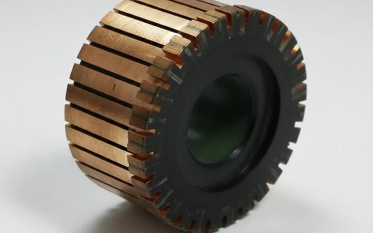
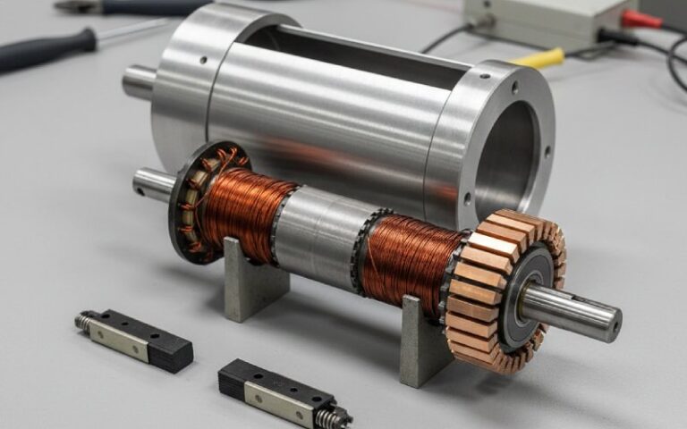
A commutator segment is an individual conductive bar in a commutator assembly, typically made of copper and insulated from adjacent bars. In a DC motor, each segment connects the armature winding to the brush system, allowing current to transfer in sequence as the rotor turns.
For a manufacturer, that is only the starting point. A segment is not just a copper bar. It is a controlled current-transfer surface, a dimensional part, an insulation boundary, and a reliability point that directly affects brush wear, commutation stability, and service life.
Table of Contents
Commutator Segment Function in DC Motors
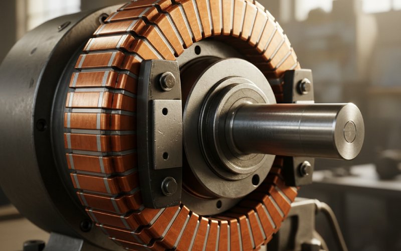
At operating speed, the segment does two jobs at once.
First, it provides the electrical path between the rotating winding and the stationary brush. Second, it defines the switching moment when current passes from one coil path to the next. That handoff is brief, but not forgiving. If segment geometry, insulation spacing, surface finish, or bar-to-bar consistency drifts out of range, the brush sees it immediately.
This is why segment quality is rarely judged by appearance alone. A commutator can look acceptable and still produce unstable contact, uneven film formation, rising temperature, or scattered sparking under load.
In production terms, the segment is one of the parts where electrical design and machining discipline meet in a very small area.
Commutator Segment Materials and Insulation Structure
Most commutator segments are based on high-conductivity copper, while adjacent bars are separated by heat-resistant insulation. The material combination is straightforward. The control is not.
From a manufacturing perspective, the segment structure has to balance several things at the same time:
- electrical conductivity
- wear resistance at the brush track
- dimensional stability during assembly
- insulation reliability between adjacent bars
- resistance to thermal cycling in service
For OEM projects, material selection usually depends on operating current, speed, duty cycle, brush grade, and the expected thermal load. A segment design that performs well in a low-load appliance motor may not hold the same margin in a high-current automotive or industrial application.
That is why serious commutator production is never only about copper purity. It is also about how the copper, insulation system, and assembly structure behave together after repeated heating, friction, and current reversal.
Key Manufacturing Requirements for Commutator Segments
Buyers often ask for drawings, dimensions, and sample lead time first. Fair enough. But in actual motor performance, a few manufacturing details matter more than a long specification sheet.
1. Bar-to-bar consistency
Each segment has to remain consistent in height, spacing, and electrical connection quality. One unstable bar can disturb the brush path and begin a wider commutation problem.
2. Surface finish on the running face
The brush does not read your tolerance report. It reads the surface. If the segment face is too rough, has burrs, or carries edge damage after machining, contact stability drops fast.
3. Concentricity of the commutator surface
Poor concentricity increases brush vibration, uneven wear, and local heating. In higher-speed applications, even small geometric variation starts to show up as noise, dust, and premature brush loss.
4. Insulation integrity between segments
Electrical separation has to remain stable under operating temperature, pressure, and contamination exposure. Segment insulation is not a passive filler. It is part of the reliability structure.
5. Connection quality between segment and winding
A commutator segment is only as good as its electrical connection to the armature circuit. Weak joints, local resistance rise, or unstable bonding conditions usually appear later as heating, dark bars, or uneven current distribution.
For this reason, a capable supplier should be able to discuss not only drawing dimensions, but also process control on concentricity, insulation fit, slot cleanliness, surface finishing, and connection stability.
Common Commutator Segment Defects and QC Checkpoints
This is where a manufacturer should speak clearly. Not from a repair-shop angle. From a prevention angle.
| Issue observed during inspection or operation | Likely segment-level cause | Manufacturing or QC focus |
|---|---|---|
| Uneven brush wear | bar height variation, poor concentricity, rough surface | turning accuracy, runout control, final surface inspection |
| Local overheating on one or several bars | high resistance joint, poor current distribution, unstable contact area | connection reliability, resistance consistency, bar-to-bar check |
| Scattered sparking at the brush track | burrs, edge defects, unstable insulation height, poor bar geometry | deburring, chamfer control, insulation finishing, track inspection |
| Carbon dust accumulation and unstable film | slot contamination, rough machining, poor segment edge condition | cleaning process, slot inspection, finishing control |
| Noise and brush chatter | eccentric running surface, bar irregularity, mechanical instability | concentricity verification, dynamic balance support, dimensional consistency |
| Early commutator wear in service | unsuitable material match, weak surface control, overload mismatch | material review, application review, surface and hardness control |
In our production logic, defects are not grouped as “electrical” or “mechanical” first. That split is too clean for real motors. A segment problem usually crosses both. Slight bar variation becomes unstable contact. Unstable contact becomes heat. Heat shifts film behavior. Then wear accelerates. By the time the motor is opened, the original cause is already buried under secondary damage.
That is why front-end process control matters more than back-end explanation.
Why Mica Undercut and Segment Edge Finish Still Matter
On paper, these are small details. In service, they are not.
If insulation stands too high relative to the copper surface, the brush contact becomes less stable. If the segment edge is left sharp after machining, brush wear and film disturbance increase. If slot debris remains after finishing, the risk of bar-to-bar trouble rises.
None of this is exotic. Still, these are among the first places where low-end production starts to show.
For buyers comparing suppliers, this matters because two commutators can share the same outer dimensions and still behave very differently in operation. Geometry on the drawing is only part of the story. Finish quality, slot condition, insulation control, and running-surface consistency decide whether the product will remain stable after installation.
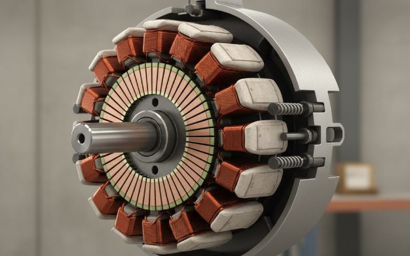
How Segment Count and Design Affect Motor Performance
Segment count is often treated as a design-side topic only. It should not be.
More segments can support smoother current transfer and reduce the electrical step seen during switching. At the same time, higher segment count means narrower bars, tighter manufacturing windows, and less room for variation in assembly and finishing.
So there is always a trade-off.
For the customer, this means the right commutator segment design depends on more than motor size. It depends on:
- speed range
- current density
- brush system
- space limit inside the motor
- expected life target
- thermal cycling conditions
- cost target for volume production
A supplier that only asks for the commutator diameter and segment quantity is not asking enough.
How to Evaluate a Commutator Segment Supplier
If you are sourcing commutator segments for OEM production, sample approval should not stop at fitment.
A more useful supplier review usually includes these questions:
Can the supplier control dimensional consistency in mass production?
Prototype quality is easy. Stable output over batches is the real question.
Can the supplier match material and insulation structure to the application?
A standard segment is not always the right segment, especially for high-load or high-speed motors.
Can the supplier discuss failure prevention, not only product dimensions?
A manufacturer should be able to explain how its process reduces brush instability, local heating, and early wear risk.
Can the supplier support custom commutator segment development?
For many motor programs, standard catalog sizes are only a starting point. OEM projects often require changes in segment count, copper specification, insulation layout, hook structure, or assembly form.
Can the supplier support engineering communication clearly?
The ability to review drawings, confirm manufacturability, and align tolerances early usually saves more time than fast quotation alone.
Custom Commutator Segments for OEM Applications
For OEM and replacement-motor programs, custom design is often the practical route.
A custom commutator segment solution may be required when the motor has:
- limited installation space
- unusual brush geometry
- higher current loading
- demanding speed stability
- strict life-cycle targets
- special assembly requirements
In these cases, the segment should be developed as part of the motor system, not as an isolated copper component.
From the manufacturing side, custom work usually starts with the drawing set, electrical parameters, target application, and expected annual volume. Once those are clear, segment structure, material route, and production feasibility can be reviewed in a way that is useful for both engineering and purchasing teams.
Why Manufacturer-Level Quality Control Matters
A commutator segment is a small part. It can still decide whether the finished motor runs cleanly or creates warranty problems.
That is why quality control should cover more than outgoing inspection. It should begin with material selection, continue through forming and machining, and stay active through insulation fitting, assembly, finishing, and final verification.
From a buyer’s side, the value of this approach is simple: fewer hidden variables after assembly.
From a factory side, the rule is also simple: if segment consistency is unstable, motor consistency will not be stable either.
FAQ About Commutator Segments
What is the difference between a commutator and a commutator segment?
A commutator is the complete assembly mounted on the rotor. A commutator segment is one individual conductive bar within that assembly.
What material is used for commutator segments?
Commutator segments are typically made from high-conductivity copper, while insulation between segments is designed to withstand heat, pressure, and electrical separation requirements.
Why is insulation between commutator segments important?
Without proper insulation, adjacent bars can lose electrical separation, which increases the risk of shorting, unstable commutation, heating, and reduced motor life.
What causes commutator segment failure?
Common causes include poor surface finish, bar height variation, weak electrical connection, contamination, unstable insulation condition, overload, and poor application matching.
Can commutator segments be customized?
Yes. For OEM motor projects, commutator segments are often customized based on dimensions, segment count, material selection, insulation structure, and application-specific operating conditions.
What should buyers check when sourcing commutator segments?
Buyers should review dimensional control, material suitability, insulation reliability, surface finish, batch consistency, manufacturability support, and the supplier’s ability to support technical discussion beyond quotation.
Need a Reliable Commutator Segment Supplier?
If you are developing a new motor or qualifying an alternative source, the segment should be reviewed as a performance part, not just a drawing item.
Our engineering team supports OEM and custom commutator segment projects based on application data, drawings, and production targets. If you need help with design review, sample evaluation, or mass-production feasibility, contact us for technical support.