What Is a Commutator Motor? A Deep, Practical Guide
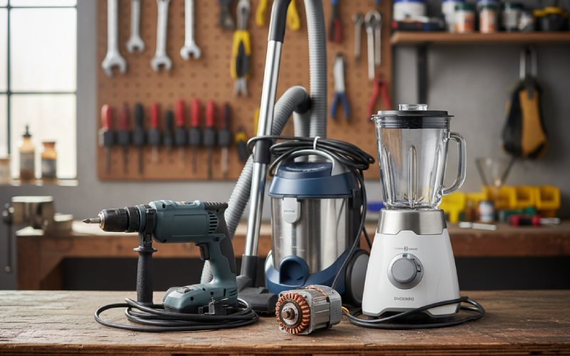
If you have ever squeezed a drill’s trigger, heard a blender scream to life, or watched a vacuum cleaner wheels-up on the carpet, you have probably used a commutator motor without realising it. These motors are small, loud, slightly spark-prone, and absolutely everywhere in everyday tools and appliances.
This guide walks through what a commutator motor actually is, how it works in plain language, where it shines, where it struggles, and how it compares to newer brushless technologies. The goal is not just to define a few terms, but to give you enough intuition that you can look at a motor and have a good sense of why it was designed that way.
Table of Contents
Simple definition: what is a commutator motor?
A commutator motor is any electric motor that uses a mechanical commutator and brushes to feed current into the rotating part of the machine and to reverse that current at just the right moments, so the shaft keeps turning in one direction. The commutator is a segmented copper ring mounted on the rotor (armature), and carbon brushes press against it to make sliding electrical contact. As the rotor spins, different segments connect to the external circuit, which flips the direction of current in the coils every half-turn and maintains a continuous torque.
In other words, a commutator motor is defined less by its power supply (AC or DC) and more by its method of switching current: it uses a physical, rotating switch, not electronics. Classic DC motors, universal motors in power tools, and some specialised AC motors all fall into this “commutator motor” family.
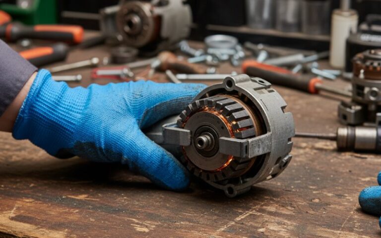
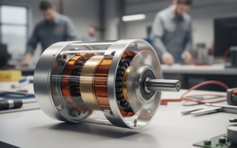
The key pieces: stator, rotor, commutator, brushes
To understand why commutator motors behave the way they do, it helps to picture their main parts working together like a small mechanical orchestra.
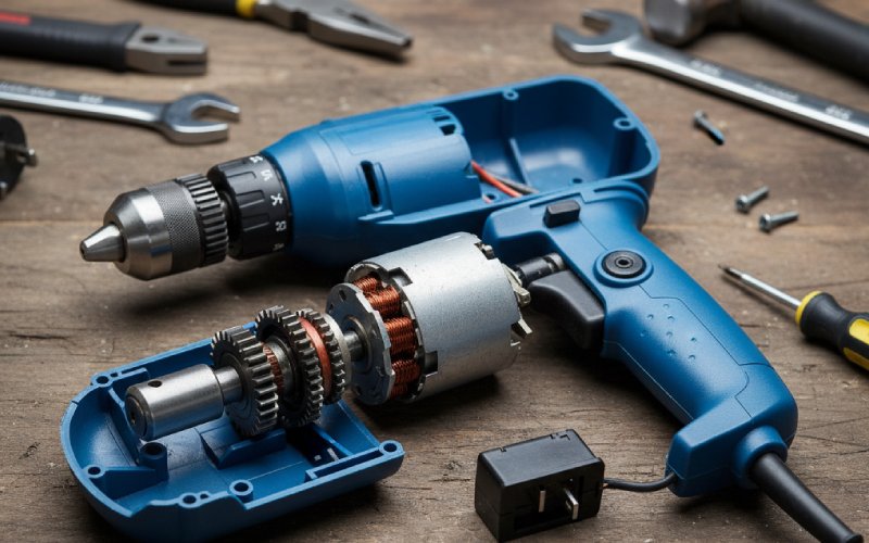
The stator is the stationary part of the motor. It provides the magnetic field, either with permanent magnets or with coils of wire called field windings.
The rotor, also called the armature, is the spinning part mounted on the shaft. The rotor carries coils of wire that cut through the magnetic field and produce torque when current flows through them.
The commutator is a copper cylinder divided into insulated segments. Each coil on the rotor connects to a pair of these segments.
The brushes are blocks of carbon or graphite pressed against the commutator by springs. They carry current between the outside world and the spinning commutator segments.
Together, these four elements create a neat trick: they constantly change which coil is energised and which way current flows, exactly when the rotor needs a “push” to keep spinning.
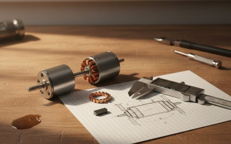
How a commutator motor actually works
Imagine a very simple motor: a single rectangular coil of wire sitting between the north and south poles of a magnet. When current flows through the coil, one side of the loop experiences a force upward and the other side experiences a force downward. That pair of forces creates a torque and the coil starts to turn.
Very quickly, though, the coil would rotate until its plane aligns with the magnetic field, at which point the forces vanish. Worse, if the current kept flowing in the same direction, the forces would reverse as the coil moves past this point and the torque would try to spin the motor backwards.
The commutator and brushes solve this elegantly. As the rotor approaches that “dead” position where torque would reverse, the brushes slide from one pair of commutator segments to the next. The internal wiring of the rotor coils means that at this moment the current through the active coil flips direction. The magnetic field from the coil flips with it, so the torque continues to push in the same rotational direction instead of reversing.
Two important things are happening during this switch. First, the coil is briefly short-circuited between two adjacent commutator bars under the brush. Second, the current reverses while the induced voltage in the coil is also changing sign. Good commutator design tries to time this so that sparking and arcing are minimised and the motor runs smoothly.
Scale this idea up to many coils spaced around the rotor and many commutator segments, and you get a motor that produces nearly continuous torque and runs much more smoothly than that single-coil toy version.
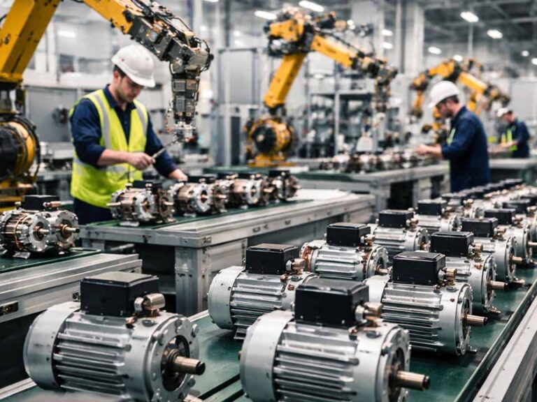
Types of commutator motors
Engineers use the phrase “commutator motor” in a few slightly different ways, but practically you will encounter three major families.
DC commutator motors
These are the classic brushed DC motors where the supply is direct current, the field may be provided by permanent magnets or DC field windings, and the commutator handles all the switching on the rotor. They come in shunt, series, and compound configurations, depending on how the field windings are connected, which allows designers to trade off between speed regulation and starting torque.
Permanent-magnet brushed DC motors are common in automotive systems, toys, small pumps, and low-power drives. Wound-field DC motors appear in traction, hoists, and industrial drives where precise speed control used to be critical before modern electronics took over.
Universal motors (AC commutator motors)
A universal motor is a commutator motor designed so that it can run on either AC or DC supply. Internally it looks very similar to a DC series motor, but with tweaks such as laminated cores and sometimes compensating windings to handle alternating current without excessive losses or poor commutation.
Because the field windings and the armature windings are in series, when AC reverses direction, both magnetic fields reverse together. The torque therefore stays in the same direction, and the motor continues to spin rather than “shuddering” with the mains frequency. These motors can run at extremely high speeds and have huge starting torque relative to their size, which is exactly what you want in things like drills, grinders, blender motors, and vacuum cleaners.
Special AC commutator motors (repulsion types)
Before modern capacitors and electronics were cheap, engineers developed clever single-phase AC motors that still used commutators to get high starting torque. Examples include repulsion motors and repulsion-start induction motors. In a repulsion motor, the stator looks like an AC induction motor, but the rotor is wound like a DC armature and connected to a commutator whose brushes are shorted together rather than connected to the supply. Transformer action induces currents into the rotor, and the geometry of the brushes creates a strong starting torque by repulsion between the rotor and stator fields. Once up to speed, some designs lift the brushes and the motor runs like a standard induction motor.
These specialised AC commutator motors are less common today but are still important historically and in certain niche applications.
How commutator motors compare to induction and brushless motors
To see when a commutator motor is the right choice, it helps to compare it with two big alternatives: induction motors and brushless DC motors.
Here is a concise comparison.
| Feature | Commutator DC Motor | Universal (AC commutator) Motor | Induction or Brushless Motor |
| How the rotor is fed | Mechanical commutator and brushes supply current to coils on the rotor. | Same commutator-and-brush system, but designed to work with AC and DC. | Rotor is fed by induction or permanent magnets; current switching is done electromagnetically or electronically. |
| Typical power supply | DC supply or rectified DC from power electronics. | AC mains or DC; often used directly on household AC. | Mostly AC for induction; electronically controlled DC for brushless motors. |
| Speed capability | Moderate to high speeds, limited by mechanical commutator. | Very high speeds, often far above mains frequency, ideal for compact high-speed tools. | High speeds for both induction and brushless, with fewer mechanical limits in brushless designs. |
| Starting torque | Can be very high, especially in series-wound designs. | Very high starting torque for size, excellent for appliances and tools. | Induction motors have good starting torque with proper design; brushless motors can be optimised in software for almost any torque profile. |
| Efficiency | Lower than comparable brushless or modern AC machines because of brush and commutator losses. | Typically modest efficiency, especially in small sizes; some energy is lost as heat and noise. | Induction and brushless motors can reach high efficiencies since there are no sliding electrical contacts and commutation can be optimised electronically. |
| Maintenance and lifetime | Brushes and commutator wear, requiring periodic replacement or resurfacing. | Brushes wear and motors can be noisy and spark, making them less suited to continuous heavy use. | Very low maintenance; no brushes, and rotor often has no windings. Bearings usually become the main wear item. |
| Typical applications | Traction drives, older industrial control systems, automotive actuators, small DC drives. | Power tools, blenders, mixers, vacuum cleaners, hair dryers, and other portable appliances. | Fans, pumps, compressors, modern EV motors, HVAC systems, and almost all high-reliability industrial drives. |
The table makes one big theme clear: commutator motors trade efficiency and maintenance for simplicity, brutal starting torque, and high power in a small package.
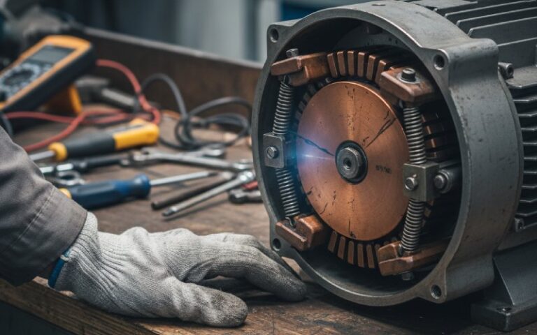
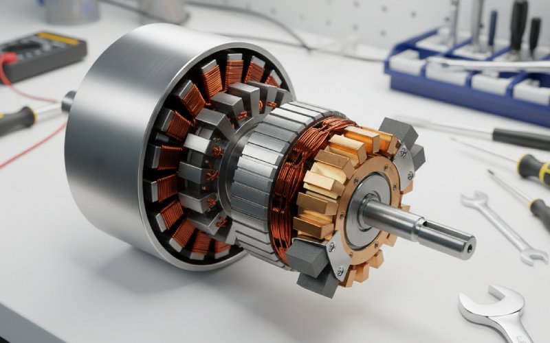
Inside the commutator itself
If you zoom in on the commutator, it is more than just a copper “drum.” Each segment is a bar of copper insulated from its neighbours, traditionally with mica and now also with various plastics in smaller machines. Every armature coil is soldered or welded to one or more of these segments.
As the motor size and voltage increase, more segments are used. Large industrial DC machines can have hundreds of segments to keep the voltage between adjacent bars low and to make the current reversal smoother. The segments are held together mechanically like dovetail bricks, and the whole assembly must be extremely round and balanced, or the brushes will bounce and spark.
The brushes themselves are usually made from carbon or graphite mixtures. Their resistance is small but not zero, and that deliberate bit of resistance helps soften the current reversal during commutation and reduce arcing. Over time, the brushes wear down like pencil erasers and deposit a dark film on the commutator, which can actually help conduction if it is even and not burned.
Engineers also pay attention to the “commutating plane,” the exact angular position where the brushes touch the commutator relative to the magnetic field. Under load, the rotor’s own magnetic field distorts the main field, and the ideal commutation point shifts. In older machines, technicians literally rotated the brush assembly while the motor was running to minimise sparking, a process known as “rocking the brushes.”
Why commutator motors are noisy and spark
If you have ever looked into the vent slots of a power drill while it is running, you may have seen a miniature fireworks show. That sparking is tied directly to what makes commutator motors work at all.
During commutation, the brush briefly bridges two adjacent commutator segments. The coil connected between those segments has current flowing through it, and the commutation process tries to force that current to reverse quickly. The inductance of the coil resists this change, creating voltage spikes and causing small arcs where the brush breaks contact.
With good design, correct brush material, and a smooth commutator surface, the arcs are tiny and regular, and the motor has a faint “brush glow.” If the surface is rough, the brushes are worn, or the commutating plane is wrong, the arcs become much larger. That produces:
First, electrical noise that can interfere with radios or sensitive electronics nearby.
Second, higher brush and commutator wear, leading to maintenance issues.
Third, a potential ignition source in dusty or explosive atmospheres, which is why commutator motors are generally avoided in those environments.
The audible noise you hear from a universal motor is partly this sparking, partly brush friction, and partly the high-frequency whine of the rotor spinning at thousands of revolutions per minute.
Where commutator motors are still the right answer
Despite their quirks, commutator motors remain the best fit in several scenarios where a simple induction motor would struggle and a brushless system would be overkill or too expensive.
They excel when you need very high starting torque in a compact, low-cost package. A handheld drill or grinder must be light and small, but it also needs to deliver serious torque the instant you pull the trigger. A universal commutator motor can do that while running happily from standard AC mains.
They are very good when variable speed is required with simple, cheap control. Speed control of a universal motor using a basic thyristor or triac circuit is straightforward and has been used for decades in things like food mixers and dimmer-style motor controls.
They can be attractive for portable or battery-powered equipment where a straightforward brushed DC motor delivers enough performance without the cost of a brushless controller. That is why many legacy automotive actuators, small pumps, and hobby motors still use brushed DC constructions.
The trend: from commutator to brushless
In many larger or long-life applications, commutator motors are being steadily replaced by brushless DC and AC induction designs. There are a few reasons for this shift.
First, the sliding contact between brush and commutator introduces friction, heat, voltage drop, and wear. It caps the efficiency and lifetime of the motor and makes high-reliability, sealed designs difficult or impossible.
Second, modern power electronics are cheap and powerful. Instead of letting a mechanical commutator switch the current, designers use solid-state devices such as MOSFETs or IGBTs along with rotor position sensing or sensorless algorithms. The result is a brushless DC motor where the stator carries all the windings and the rotor is just a magnet. Efficiency improves, maintenance almost disappears, and control of speed and torque becomes extremely precise.
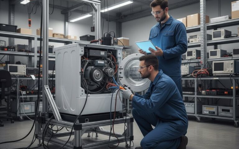
Third, regulatory and customer pressure for quieter, more efficient, longer-lasting appliances favours brushless technology. You can see this in the marketing of “inverter” washing machines, “digital” fridge compressors, and high-end cordless tools, almost all of which hide a brushless motor and its electronics inside.
Even so, commutator motors will probably persist for a long time in cost-sensitive, intermittently used tools and small machines where their simplicity still wins.
Common practical questions
Is a commutator motor the same as a DC motor?
Every classic brushed DC motor is a commutator motor, but not every commutator motor runs only on DC. Universal motors and certain AC repulsion motors are also commutator motors because they use the same mechanical switching principle on the rotor. The term “commutator motor” is therefore broader than just “DC motor.”
Why do commutator motors wear out faster than other types?
They include components whose entire job is to rub against each other: the brushes and commutator. Over thousands of hours, that rubbing erodes the brushes, roughens the commutator surface, and can eventually damage the copper segments if the motor is overloaded or dirty. Induction and brushless motors avoid this sliding electrical contact, so their main wear item is usually just the bearings.
Can I replace a commutator motor with a brushless motor directly?
Electrically and mechanically, it is not a drop-in swap. A brushless motor requires a dedicated electronic controller instead of a simple mains or DC connection, and the speed-torque curve may be very different from the original universal or DC motor. However, many modern appliances and power tools are designed from scratch with brushless systems to mimic or exceed the behaviour of older commutator motors while gaining efficiency and lifetime.
Wrapping up
A commutator motor is one of those inventions that is both beautifully simple and slightly brutal. It uses a rotating copper switch and some blocks of carbon to juggle amps and magnetic fields at thousands of revolutions per minute, turning electricity into hard, usable mechanical work.
Understanding the stator, rotor, commutator, and brushes, along with the logic behind current reversal, lets you see why these machines are compact, torquey, and noisy, and why the world is slowly but surely moving toward brushless designs.