What Is a Commutator in a DC Motor?
A commutator in a DC motor is the segmented conductive ring fixed to the armature. Brushes ride on its surface. As the rotor turns, that segmented ring switches the armature coils through the DC supply in the correct sequence, so the motor keeps producing torque in one direction instead of trying to stop and reverse itself. Also worth saying plainly: this applies to brushed DC motors. Brushless DC motors move the same timing job into electronics, so there is no mechanical commutator there.
In real machines, the commutator is not just a “reverse switch.” It is the timed contact surface between a stationary power path and a rotating winding set. During operation, a brush briefly bridges adjacent bars, one coil enters a commutation interval, that coil is momentarily shorted, its current decays, then reverses as the brush leaves the segment. Small machines usually live with this as resistive commutation. Larger machines often need extra help, like interpoles, because plain commutation starts to spark too much under load.
Table of Contents
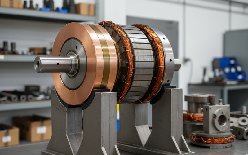
The part itself, not the simplified drawing
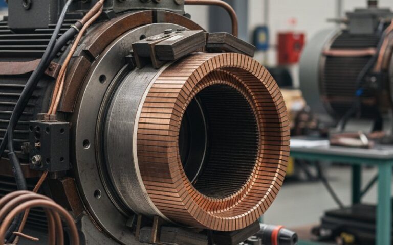
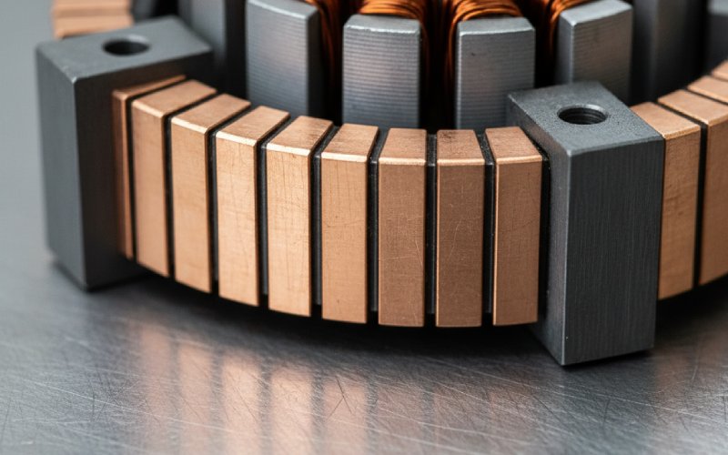
In factory terms, a DC motor commutator is usually built from multiple copper segments arranged around the rotor and insulated from one another. Those segments connect to the armature windings. The brushes, typically carbon-based in modern machines, press against the rotating surface and transfer current into the correct bars as the rotor moves. Copper conducts. Carbon survives the sliding contact better. That tradeoff is the whole story, or close enough.
The insulation between bars matters more than many buyers expect. In larger machines it is often mica-based, and on some molded constructions it may be part of the formed insulating structure. If that insulation sits too high, is poorly undercut, or collects debris between bars, the brush stops tracking cleanly. Then the trouble starts: vibration, unstable contact, leakage from bar to bar, more arcing, faster wear. Not dramatic at first. Then expensive.
How the commutator actually keeps the motor turning
A brushed DC motor needs the armature current to be redirected as rotor position changes. In the simple two-pole explanation, that happens every half turn. In a practical segmented armature, it happens coil by coil as each bar pair passes under the brush. That is why the commutator has segments instead of one continuous ring. A continuous ring would transfer power. A segmented ring transfers power and switching. Different job.
This is also why commutators are always a compromise. They make brushed DC motors easy to drive from a DC supply, and they give straightforward speed control. But the same sliding contact adds friction, brush dust, contact drop, wear, and electrical noise. So the commutator is both the reason the motor works and, often, the first maintenance item that limits service life.
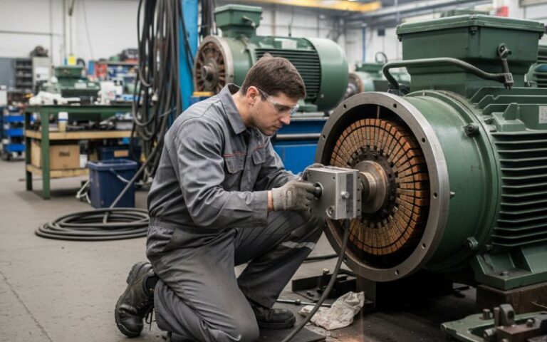
What we watch first during commutator inspection
The table below is the short version of what actually decides whether a commutator runs cleanly or eats brushes.
| Inspection point | Why it matters | What failure usually looks like |
|---|---|---|
| Copper bar surface | Carries brush contact and current transfer | Pitting, burning, rough tracking, uneven film |
| Bar-to-bar insulation | Prevents leakage and shorting between segments | Carbon tracking, slot contamination, ring fire risk |
| Mica undercut quality | Keeps brush riding on copper, not on raised insulation | Vibration, sparking, brush chatter |
| Roundness and bar height | Holds brush contact stable at speed | High bars, flat spots, broken brushes, arcing |
| Spring pressure and brush freedom | Keeps current density and contact drop under control | Hot brushes, uneven wear, poor commutation |
| Coil-to-bar connection | Delivers armature current into the correct segment pair | Local burning, repeated arcing on the same bars |
These are not theoretical edge cases. High mica, copper burrs after undercutting, dirt-packed slots, out-of-round commutators, incorrect spring pressure, binding brush holders, overload, and winding faults are all established causes of brush arcing and rapid wear.
Why commutators spark
Some sparking at a brushed commutator is part of the switching event. Excessive sparking is not.
The usual causes are boring, which is useful. Poor brush contact. Brush wear. Uneven spring pressure. Holders set too far from the surface. High mica. Burrs left in the slots. Dirt or oil on the track. An eccentric commutator. High bars. Load swings that push current too far. Faults in armature, risers, or interpoles. Once contact becomes unstable, the inductive energy in the winding does the rest and you start seeing pitting, blackening, localized heat, and fast brush consumption.
There is another pattern buyers miss. A commutator can look acceptable at rest and fail only at speed. A bar can lift the brush just enough to break contact under operating load. Or the armature can be round when cold and not stay that way when hot. That is why static appearance alone is not enough for approval on serious duty cycles.
What the commutator tells you about motor quality
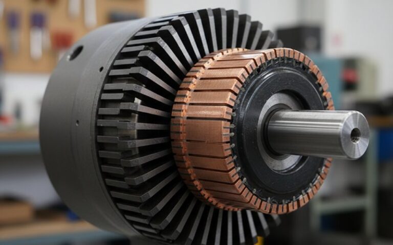
When we evaluate a brushed motor, the commutator says a lot very quickly.
A stable brownish running film, even brush seating, clean slots, consistent bar face color, and no localized burning usually point to decent geometry and balanced current sharing. Repeated damage on the same bars points somewhere else: winding connection, bar height, spring force, holder alignment, or contamination. The commutator is not just one component. It is a record of what the whole motor has been doing.
For sourcing, this matters. A low-cost commutator can still pass a basic spin test and fail later because the bar geometry, insulation finish, concentricity, or slot condition was marginal from the start. That is why serious commutator work is not only about copper grade. It is about dimensional control, slot finish, assembly tightness, balance, and how the brush system behaves once current is real and speed is real.
One more thing buyers often ask: commutator vs. slip ring
They are not interchangeable.
A slip ring is continuous. Its job is to keep an electrical path into a rotating part without switching the current path from segment to segment. A commutator is segmented on purpose so it can redirect current in the armature as rotor position changes. If the application needs timed reversal in a brushed DC armature, a slip ring does not replace a commutator.
FAQ
1. What is the main function of a commutator in a DC motor?
Its main function is to switch armature current at the right rotor position so the motor keeps producing unidirectional torque from a DC supply. In practical machines, that switching happens segment by segment through the brush contact area.
2. Does every DC motor have a commutator?
No. Brushed DC motors use a mechanical commutator and brushes. Brushless DC motors perform commutation electronically, so they do not use a commutator.
3. Why are commutators made with copper segments and insulation between them?
The copper segments carry current efficiently, while the insulation keeps adjacent bars electrically separate so the brush can switch from one segment to the next without bar-to-bar shorting. In many larger machines, mica remains a common insulating material between segments.
4. Why does a commutator wear out?
Because it is a sliding electrical interface. The brush rubs on the copper surface, which creates friction, heat, dust, and contact erosion. Arcing during poor commutation speeds that up. So wear is built into the design; the question is how controlled it is.
5. What are the first signs of a bad commutator?
Look for excessive sparking, blackened or burned bars, pitting, rough surface finish, high mica, slot contamination, hot brushes, and uneven wear patterns. Out-of-round surfaces and high bars are common root causes behind those visible signs.
6. Can a damaged commutator be repaired?
Sometimes, yes. Larger industrial commutators may be resurfaced, undercut, or have damaged segments replaced. Small molded commutators in low-cost motors are often treated as non-repair parts and replaced with the armature or the motor itself.
7. Is a commutator the same as a split ring?
In basic motor teaching, yes, the simple commutator is often described as a split ring. In actual production motors, the part is usually a multi-segment commutator, not just two halves, because real armatures need staged switching across many coils.
8. What should a buyer ask a commutator supplier?
Ask about segment concentricity, bar height consistency, insulation quality, undercut condition, slot cleanliness, coil-to-bar joint integrity, and how the assembly behaves under speed and load. Those are the details most directly tied to arcing, brush life, and field reliability.