What Would Happen If There Was No Split Ring Commutator?
Removing a split ring commutator doesn’t just break a DC motor. It quietly rewrites torque profiles, starting behavior, thermal limits, brush life, and even your maintenance model.
Let’s walk through what actually happens when that copper ring disappears — and what that means if you’re sourcing motors or commutators for real equipment.
Table of Contents
1. What the split ring really fixes (short version)
No long recap:
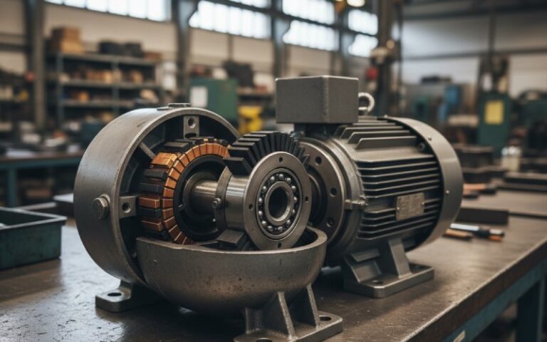
- A commutator is a rotary electrical switch that periodically reverses current between rotor and external circuit in DC machines.
- In a DC motor, the split ring version reverses the armature current every half turn so that the torque on the coil keeps the same sign and rotation stays one-way.
So it’s not “a nice accessory”. It is the mechanical implementation of commutation in a brushed DC motor.
Take it away and you’ve removed the commutation system. Not just a part.
2. Remove the split ring: what the motor actually does
Imagine a simple brushed DC motor where the rotor coil is connected through continuous rings (or hard-wired) instead of a split ring commutator.
2.1 Torque over one revolution
Without current reversal:
- For some angles, both sides of the coil produce torque in the same rotational direction.
- For two specific orientations each half-turn, the forces on the two sides of the coil line up so the net torque is zero. These are equilibrium positions (one stable, one unstable).
- Between those points, the torque reverses sign. So whatever rotation you built up is now being undone.
The motor becomes an electromechanical pendulum:
- It speeds up toward one equilibrium point.
- Slows down as torque weakens.
- Reaches zero torque.
- Overshoots slightly due to inertia.
- Sees torque in the opposite direction.
- Swings back.
In an ideal world without friction, you get continuous oscillation back and forth. With friction, the motion damps out and the rotor parks at the stable zero-torque position.
2.2 “No split ring” in a DC motor = no useful motor
So, practically:
- Starting: If the rotor is already near the stable equilibrium position when you apply power, it probably doesn’t move at all.
- Under load: Any oscillation is tiny compared with the load inertia. Shaft looks stationary. Current is there, torque is not.
- Outcome: Heat, brush wear, no real mechanical work.
That’s why educational resources summarise it as:
the motor would oscillate or stop instead of rotating continuously, so it’s non-functional as a DC motor.
Not wrong. Just simplified.
3. With vs. without split ring commutator: side-by-side
Same magnetic circuit. Same supply. Only the split ring changes.
| Aspect | With split ring commutator | Same machine, no split ring |
|---|---|---|
| Current in armature | Reversed every half-turn | Fixed polarity |
| Net torque sign | Stays one direction | Flips sign each half revolution |
| Motion profile | Smooth continuous rotation | Oscillation or stall at equilibrium |
| Startup behavior | High chance of self-start | Often stuck at stable zero-torque position |
| Effective shaft output | Usable rotary power | Negligible, mostly vibration |
| Thermal profile | Heating mostly proportional to mechanical load | Heating mostly from I²R with little mechanical work; easy to overload windings |
| Noise & vibration | Mostly from commutation and bearings | Low speed, “buzzing” or low-frequency rocking |
| System-level result | Motor | Warm, humming brake with wires |
If you’re buying motors for pumps, fans, conveyors, or tools, everything on the right-hand column is a polite way of saying: the machine doesn’t do its job.
4. How that failure looks in real applications
The physics is one thing. The plant floor is another.
Remove the split ring from a brushed DC topology and drop that into typical B2B scenarios:
4.1 Conveyors and material handling
- Expected: Steady torque, near-constant direction, ability to start under load.
- Observed without commutator:
- Belt bumps a few millimetres, rocks back, then stops.
- Motor current remains high; the drive or fuse sees it as near-locked-rotor.
- Thermal model you used when you sized the frame is now wrong; you’re basically feeding copper losses into a stationary rotor.
On paper: efficiency collapses. In the warehouse: the line just “doesn’t move”.
4.2 Pumps, fans, blowers
- Instead of continuous rotation, you get a small angular oscillation.
- For a centrifugal pump or fan, that barely moves fluid or air. Flow curves become meaningless.
- The system control loop thinks it commanded speed, but you only changed heating rate.
So the mechanical system is still. Only the electricity moves.
4.3 Power tools and small appliances
Hand tools, vacuums, mixers, many of them still rely on brushed machines (sometimes universal). If you somehow removed the commutator function but kept DC supply:
- The rotor tries to move into a minimum-energy position and stay there.
- End user hears a hum, maybe a tiny twitch, no spin.
- Brushes spark more because the contacts sit on the same segments under high current, not sweeping.
The failure looks like a classic “burned armature” case, just without the dramatic smell (at least for the first few tests).
4.4 Automotive & transport auxiliaries
Starter motors, fuel pumps, blower motors, wipers — many designs still use commutators.
No commutator here isn’t just “lower efficiency”; it’s:
- Engines that never crank.
- Fuel pumps that can’t build pressure.
- Rail traction motors that heat instead of pull.
From a fleet operator’s perspective: downtime, not theory.
5. “But there are motors with no commutator…”
Exactly. And that’s where the confusion usually starts.
The question “what if there was no split ring commutator” often mixes two different ideas:
- Take an existing brushed DC architecture and simply delete the split ring.
- Use a motor technology that was designed from the start with no mechanical commutator.
Those are not the same world.
5.1 Brushless DC motors (BLDC)
Brushless DC motors get rid of brushes and mechanical commutator entirely:
- Permanent magnets move to the rotor.
- Coils live on the stator.
- An electronic controller handles commutation, switching phase currents in sequence to create a rotating field.
Underneath, the topology supports that change. The magnetic and electrical design assumes electronic commutation from day one.
So when someone says “this DC motor has no commutator”, they usually mean brushless, not a brushed design with a missing copper ring.
5.2 AC induction and synchronous motors
Three-phase induction motors and many synchronous machines also run without commutators:
- The stator creates a rotating magnetic field using AC phases.
- The rotor follows that rotating field via induction (squirrel-cage) or field excitation.
- No brushes or commutators required in the common industrial versions.
But again, that’s a different machine class. You don’t “delete” the split ring in a DC motor and magically arrive at an induction motor. You redesign the entire machine: laminations, slots, supply, control.
5.3 Slip rings instead of split rings?
Some teaching examples talk about replacing the split ring with slip rings. Then the rotor sees an AC current instead of rectified DC.
Result for a DC motor geometry:
- The torque reverses with the supply frequency.
- At mains frequencies, the rotor can’t follow the direction change and mostly vibrates or hums.
Again, not a path to a clean one-direction DC drive.
6. Why commutator quality still matters (even in a “brushless future”)
You can’t just remove split rings from existing brushed machines, but you can decide how good they are.
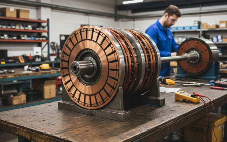
Commercial commutator manufacturers talk a lot about:
- Silver-alloy copper grades and insulation systems.
- Manufacturing methods (compression seasoning, spin seasoning) to stabilise the copper/mica pack at operating speed and temperature.
- Segment count, slot geometry, tolerances on bar movement and runout.
That’s not marketing fluff. Poor commutator geometry and material selection show up as:
- Higher brush temperature and dust.
- More arcing at the brush face.
- Shorter brush life and more frequent maintenance stops.
- Noise and RF interference.
From a procurement angle, the key point is simple and a bit blunt:
If you’re locked into a brushed DC architecture, the split ring is not optional and its quality is a primary reliability lever, not a commodity copper ring.
7. FAQ: common “no commutator” questions
Q1. Can a DC motor operate without a split ring commutator?
For a classic brushed DC motor intended for one-direction continuous rotation: no, not in any useful sense.
Without current reversal:
The torque alternates each half revolution.
The rotor either oscillates or settles at a stable equilibrium with zero net torque.
You can still feed it power and heat it up. You just don’t get practical mechanical output.
Q2. Why do some “DC” motors in products have no visible commutator?
Those are usually brushless DC motors:
No brushes, no mechanical commutator.
The stator windings are commutated electronically by an ESC or dedicated driver.
Electronics replaced the split ring; the commutation function still exists, just in silicon.
Q3. Can we replace a split ring commutator with slip rings to reduce wear?
Not directly, not in the same topology.
Slip rings are designed for continuous transfer of power or signals into a rotating part without reversing polarity.
A DC motor with slip rings feeding the rotor like an AC generator setup will see alternating torque directions and likely only vibrate.
If your goal is fewer wearing parts, the upgrade path is usually:
Move to a brushless DC motor, or
Move to an AC induction/synchronous motor plus suitable drive.
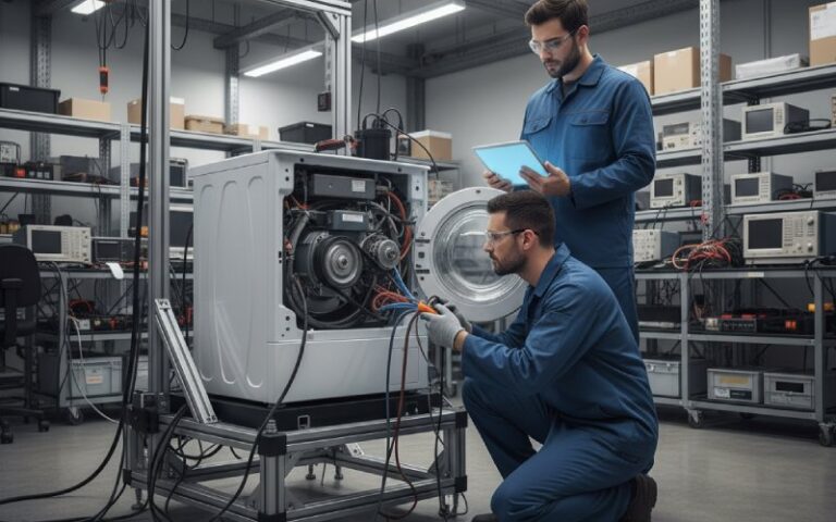
Q4. What happens if a split ring commutator is poorly manufactured or damaged?
Typical symptoms:
Uneven brush wear, local hot spots.
Excessive arcing on certain segments.
Audible “grinding” or periodic noise at commutation frequency.
Reduced insulation life from localized heating.
High-end commutator manufacturers specifically control bar tolerances, copper alloy properties, and seasoning/spin-testing to avoid segment movement at speed and temperature.
So yes, the commutator can quietly decide whether your maintenance interval is months or years.
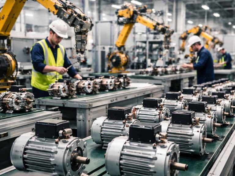
Q5. Do three-phase industrial motors use a split ring commutator?
Standard cage-rotor three-phase induction motors: no.
They rely on a rotating stator field from the three AC phases.
The rotor currents are induced, not directly switched, so no commutator or brushes are needed.
Some specialised high-power machines use more complex rotor systems, but the everyday industrial motor on a pump or fan is commutator-free by design.
8. Short summary for busy engineers
If you remember only a few points:
- In a brushed DC motor, the split ring commutator is the commutation system. Remove it and you remove continuous torque.
- Without it, the machine either oscillates or parks at a stable equilibrium while drawing current and generating heat.
- Technologies that “run without commutators” — brushless DC, induction, synchronous — are different designs, not the same DC motor with a missing ring.
- If you must stay with brushed DC, commutator design and manufacturing quality are major levers for reliability and lifecycle cost.
So the real engineering choice usually isn’t “motor with or without commutator”.
It’s “this application: robust mechanical commutation or a move to an electronic/AC architecture?”