What Is a Commutator Made Of?
If a buyer asks this question, the short answer is easy: copper and insulation.
In production, that answer is not enough. A commutator is a material stack, not a single material. The copper carries current. The insulation separates segments. The body or retention structure keeps everything in position when heat rises, speed changes, brush pressure shifts, and the motor stops being gentle.
That is why we never treat commutator material selection as a one-line item on a drawing.
Table of Contents
The material stack we actually build around
In our factory, a commutator is usually built from these material groups:
| Commutator Part | Typical Material We Use | What It Has To Do |
|---|---|---|
| Segment bars | High-conductivity copper, oxygen-free copper, or silver-bearing copper | Carry current, resist heat-related softening, hold segment shape after machining and operation |
| Segment insulation | Mica, micanite, or bonded mica insulation | Separate bars electrically, stay stable under heat and brush dust |
| Molded body or insulation support | Thermoset resin system or resin-bonded insulation structure | Hold segment geometry, insulate the copper pack from the shaft area, reduce movement under load |
| Retention structure | Steel ring, sleeve, V-ring, or reinforced support parts | Keep the bar pack tight at speed and during thermal cycling |
| Hub or bush area | Brass, steel, or fitted metal insert | Transfer assembly load to the shaft area and improve fit stability |
So yes, copper is the main contact material. But a commutator is not “made of copper.” Not in any useful manufacturing sense.
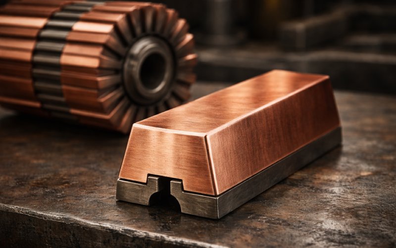
Copper is the main material. Not always the same copper.
The segment bar is usually copper because conductivity matters. That part is obvious. What matters more in production is which copper, and under what duty.
For lower-load applications, standard high-conductivity copper is often enough. For tougher operating conditions, we may move to oxygen-free copper or silver-bearing copper, especially when thermal stability matters more than paper conductivity numbers.
Why? Because the segment does not only conduct current. It also has to survive:
- repeated starting current
- local heating at the brush track
- edge stress near the slot
- machining after assembly
- dimensional drift after thermal cycling
A soft copper grade may look fine on the material sheet and still create trouble later. Smearing. Edge wear. Track instability. Segment movement that shows up first as a surface problem, then as a life problem.
That is why we do not lock copper grade from conductivity alone. We look at duty cycle first.
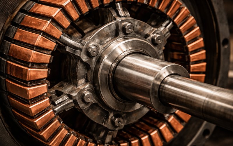
The insulation between segments is usually mica
Between commutator bars, the insulation needs to do several jobs at once. It has to block current, tolerate heat, survive pressure, and keep its thickness where we need it. That is why mica is still the standard choice in many commutator structures.
In our production work, mica-based insulation remains the practical answer for most segment-to-segment separation because it stays stable where simpler materials start to drift or age too fast.
This matters more than it seems.
When the insulation system is wrong, the failure does not always begin as a clean electrical breakdown. It may begin as:
- unstable brush contact
- uneven film formation
- dust packing in the slots
- poor undercut behavior
- accelerated edge burning
A commutator can look electrically correct and still run badly because the insulation geometry is wrong. That happens more often than buyers expect.
Resin is not filler
In molded commutators, the resin body is doing real work. It is not there to occupy empty space.
The molded body helps hold the segment pack in position, provides insulation to the shaft zone, supports concentricity, and absorbs part of the assembly stress. When the resin system is weak, too brittle, or poorly matched to the operating temperature, the commutator may lose stability long before the copper wears out.
This is one reason molded commutator design cannot be separated from application conditions.
For compact motors and controlled loads, a molded structure is often the most efficient choice. For harder duty, larger diameter, or higher mechanical stress, the structure may need extra retention support rather than relying only on the molded body.
That is not a theory issue. It is a service-life issue.
What changes between molded and built-up commutators
The question “what is a commutator made of” also depends on the commutator type.
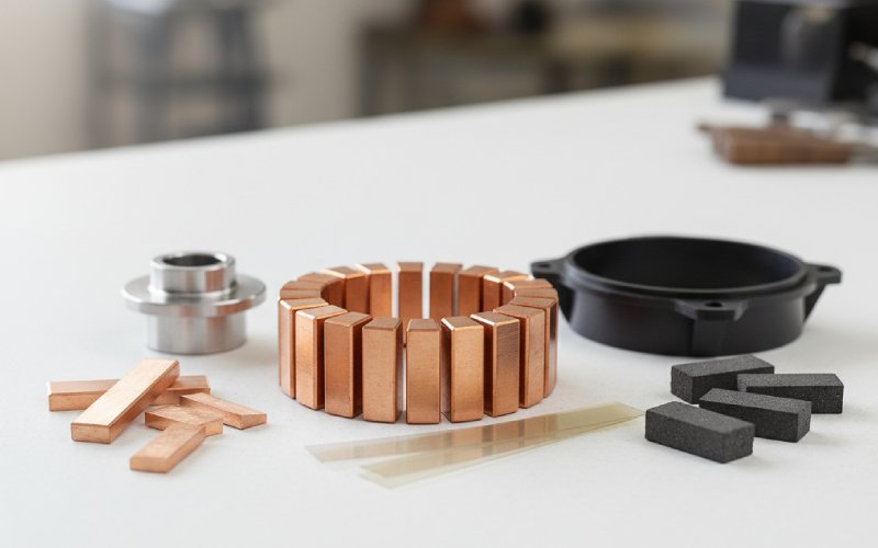
A molded commutator usually includes copper segments, inter-segment insulation, a thermoset molded body, and often a metal bush or insert in the center. This design is widely used where compact structure, consistent production, and cost control all matter at the same time.
A built-up commutator or more mechanically retained structure uses copper bars plus mica insulation, then adds rings, sleeves, or reinforced support parts to control movement. This approach makes more sense when the mechanical load is less forgiving and the copper pack needs stronger restraint.
Neither structure is universally better. The correct one depends on speed, temperature rise, brush system, shaft fit, and expected service conditions.
That is why we usually confirm application details before recommending a structure.
What the material choice is really trying to prevent
From a factory point of view, commutator material selection is less about naming materials and more about preventing failure.
The real targets are these:
1. Prevent segment softening
If the copper loses hardness too early, the track does not stay consistent. Wear behavior changes. The surface stops being predictable.
2. Prevent insulation drift
If the mica system or insulation structure moves, chips, or stands proud where it should not, brush contact becomes unstable.
3. Prevent pack movement
If the body or retention structure does not hold the bar pack tightly enough, high-speed or repeated thermal loading will start opening small dimensional changes. Small is enough.
4. Protect shaft-fit stability
A weak hub or bush area pushes stress into the wrong place. Then the assembly problem starts pretending to be a material problem.
That is why we review commutator material as a system. Not as five separate raw materials.
How we usually choose the material stack
When customers send us a drawing and ask what material the commutator should use, we do not start with the copper grade. We usually start with the operating conditions.
The first things we check are:
- motor type
- voltage and current load
- start-stop frequency
- speed range
- brush type
- target service life
- shaft fit method
- available space for the commutator structure
After that, the material decision becomes narrower and more practical.
For example:
- If the motor sees repeated current peaks, segment stability becomes more important.
- If the operating temperature is high, resin and insulation stability move higher on the priority list.
- If the unit runs faster, retention structure matters more.
- If the space is tight, the material stack has to work harder in a smaller geometry.
That is usually where bad material decisions begin too early. Someone asks for “copper commutator” as if that answers the design problem. It does not.
What buyers often miss when they compare quotes
Two commutators can look similar in drawings and still behave very differently in use.
That usually comes down to details such as:
- copper grade selection
- insulation thickness control
- molded body consistency
- undercut quality
- runout control
- retention reliability
- slot profile design
These are not decoration-level differences. They affect brush wear, temperature behavior, commutation stability, and service life.
A lower-cost commutator may still be the correct choice. Sometimes it is. But if the supplier cannot explain how the material stack fits the duty, the quote is incomplete no matter how good the unit price looks.
The practical answer
So, what is a commutator made of?
In real manufacturing terms, a commutator is made of copper segments, mica-based insulation, and a structural support system that may include resin, sleeves, rings, and metal hub components. The exact combination depends on how much electrical load, heat, speed, and mechanical stress the motor will create.
That is the answer we use on the factory side. Because that is the answer that holds up after the motor starts running.
FAQ
Is a commutator made entirely of copper?
No. Copper is the current-carrying contact material, but a working commutator also needs insulation between segments and structural support around the copper pack.
Why is mica used in a commutator?
Because it remains stable in thin sections under heat, pressure, and electrical stress. It is one of the most practical materials for separating commutator bars.
What kind of copper is used for commutators?
That depends on the application. Standard high-conductivity copper is common, but oxygen-free copper or silver-bearing copper may be used when heat stability or harder duty requires it.
What is the molded part of a commutator made of?
Usually a thermoset resin system or a similar insulation structure designed to hold the bar pack, maintain geometry, and provide electrical isolation from the shaft area.
Are molded commutators and built-up commutators made of the same materials?
They share the same core materials in principle, mainly copper and insulation, but the structural support system differs. Molded types rely more on the molded body. Built-up types use more mechanical retention parts.
Which material matters most in commutator life?
No single material decides everything. The copper, insulation, molded body, retention design, and fit structure all affect performance together. The wrong combination causes trouble faster than one weak material alone.
Need help selecting commutator material?
If you are comparing copper grades, insulation systems, or commutator structures for a new motor project, send us your drawing or operating parameters.
Our engineering team can review the application and recommend a practical commutator material stack based on the real duty, not only the drawing description.