What Does a Commutator Do in a DC Generator?
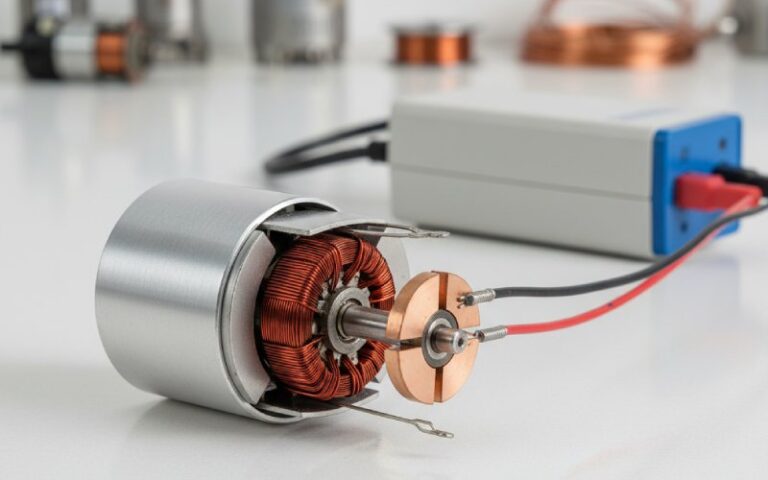
A commutator in a DC generator does not create the voltage. It makes the voltage usable. Inside the armature, the induced EMF is alternating by nature. The commutator switches each coil connection as the rotor turns, so the output at the brushes stays unidirectional at the terminals. That is the real job. Not theory for theory’s sake. That is what lets a DC generator deliver DC to the outside circuit.
In practical shop terms, the commutator is the working interface between the rotating winding and the stationary external circuit. If that interface is stable, the machine runs clean. If it is not, the first signs are usually not subtle: sparking, unstable brush contact, copper marking, heat, dust, and output that looks worse under load than it did on the bench.
Table of Contents
The short answer
A commutator in a DC generator collects current from the rotating armature and reverses coil connections at the correct point in each rotation, so the external circuit receives unidirectional DC output instead of the armature’s internal alternating waveform. In small demonstrations that output is clearly pulsating. In practical machines, more coils and more commutator segments make the output much smoother.
What the commutator actually changes in a real generator
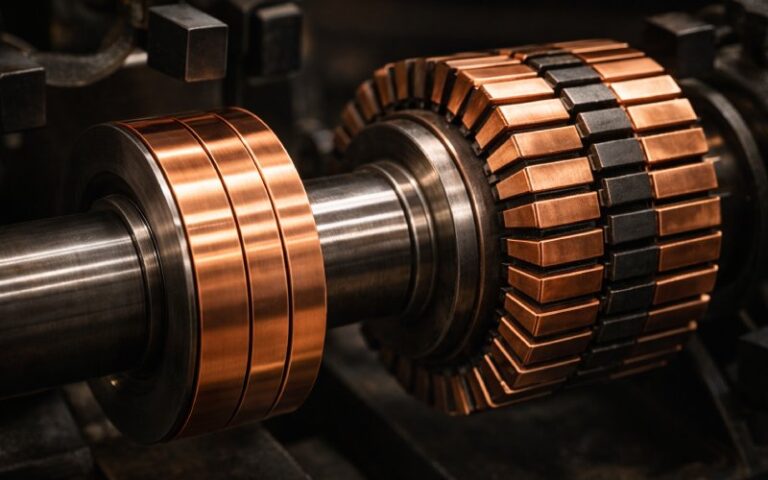
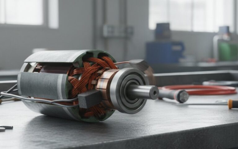
In production equipment, the commutator affects four things buyers actually care about: terminal polarity, brush behavior, current transfer, and service life. The copper segments rotate with the armature. The brushes stay fixed. As contact moves from one segment to the next, the commutator keeps the same external brush acting as the same output polarity while the coil voltage inside the armature keeps reversing with rotation.
If that switching happens cleanly, the machine behaves like a DC source. If it happens badly, the machine starts paying for it at the brush track.
Why buyers should care about commutation, not just commutators
This is where weak articles usually drift into classroom language.
A commutator is not only a copper assembly on the shaft. It is part of a commutation system. Segment geometry, insulation condition, brush grade, spring pressure, surface finish, concentricity, and the magnetic condition around the neutral zone all affect whether current reversal finishes cleanly during the brief short-circuit period under the brush. When reversal is incomplete, sparking shows up fast.
That is also why two commutators with the same outer dimensions can behave very differently in service.
One fits the drawing. The other fits the machine.
What happens during commutation
During operation, the brush briefly bridges adjacent commutator segments. For that moment, the coil under commutation is shorted through the brush path, and its current must reverse direction before the next segment fully takes over. Because the coil has inductance, that reversal resists change. Under load, that resistance to current reversal is one of the main reasons sparking becomes harder to control.
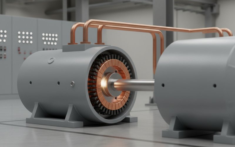
On medium and larger wound-field machines, interpoles are often used to help that reversal happen faster and more cleanly. Their purpose is simple enough: they generate the right assisting EMF in the coil being commutated so brush arcing stays under control as load rises.
If your application is heavy-duty, continuous-duty, or load-cycling, this matters more than the one-line definition.
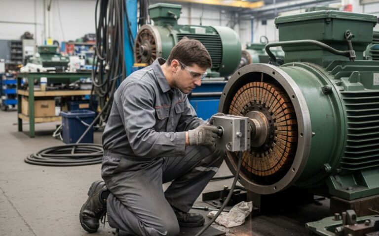
What we look at first when a customer says, “The commutator is the problem”
We usually separate the issue into three buckets:
1. Electrical transfer problem
The machine makes power, but the current does not transfer cleanly from the rotating armature to the fixed circuit. That points to brush contact, film condition, raised bars, insulation debris, poor surface condition, or an out-of-round commutator.
2. Geometry problem
The part may be dimensionally close, but not correct where it matters: runout, concentricity, segment height consistency, riser connection quality, mica undercut, or brush-track finish. Those small errors do not stay small at speed.
3. Application mismatch
The replacement part is technically a commutator, yes. But not one matched to the current density, surface speed, brush grade, duty cycle, or load profile of the actual machine. This is common in replacement sourcing. The part “fits.” Then it burns time. That is the expensive part.
Factory checkpoints that affect commutator performance
For industrial buyers, this table is more useful than another generic diagram.
| Control point | Why it matters in service | What usually happens when it is ignored |
|---|---|---|
| Copper segment consistency | Keeps current transfer even across the brush track | Uneven wear, local heating, unstable contact |
| Mica insulation and undercut | Prevents segment shorting and supports brush transition | Edge sparking, tracking, rough commutation |
| Concentricity and runout | Keeps brush pressure and contact stable at speed | Bounce, streaking, dusting, fast brush wear |
| Surface finish after machining | Supports proper film formation and smooth sliding contact | Noise, overheating, copper drag marks |
| Brush grade matching | Balances conductivity, friction, and wear behavior | High sparking, glazing, excessive carbon dust |
| Connection quality at risers/leads | Maintains current path integrity under load | Hot spots, intermittent faults, local discoloration |
| Segment count and winding match | Helps shape smoother DC output at the terminals | Higher ripple, weaker output stability |
The point is not that one factor decides everything. It usually does not. Bad commutation is often a stack-up problem. A tolerable brush grade plus a rough surface plus a little runout plus higher load. Then the customer sees sparks and thinks the copper itself is the whole story.
It rarely is.
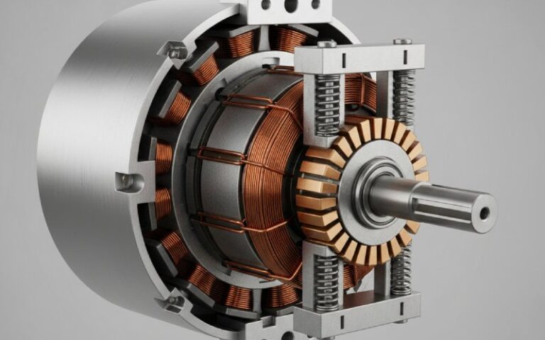
Does segment count matter?
Yes. More than many buyers expect.
A simple single-coil example produces very obvious pulsating DC. Real DC generators use multiple coils and multi-bar commutators so the terminal voltage becomes the sum of many displaced coil voltages. The result is still DC, but smoother and closer to constant. That is one reason segment count, winding layout, and brush position cannot be treated as afterthoughts in industrial designs or replacement jobs.
If your project involves waveform quality, sensitive downstream equipment, or low-speed output consistency, this section of the design deserves more attention than it usually gets.
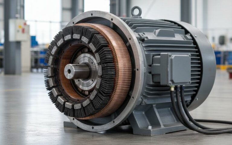
The brushes are part of the answer too
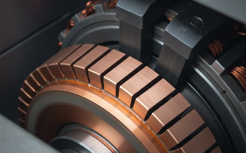
A commutator without brushes is only a rotating segmented conductor. The brushes complete the transfer to the external circuit. In common DC machine construction, the segments are copper and the brush material is typically carbon or graphite based, with the insulation between segments set below the copper surface so the brush can ride the track properly.
That is why a replacement commutator should never be evaluated alone. We normally review it together with the brush grade, brush holder condition, spring pressure, operating speed, and the customer’s actual duty pattern. Otherwise the root cause stays in the machine and the same failure repeats on the new part.
When should a commutator be repaired, and when should it be replaced?
There is no single rule, but this is how we frame it.
Re-machining may be enough when the issue is limited to light surface roughness, minor out-of-round condition, film instability, or mica that needs proper undercut and edge dressing. Full replacement becomes more likely when there is severe bar damage, loose segments, repeated burning, connection failure, structural cracking, or a mismatch between the existing commutator design and the actual application.
For sourcing teams, the important part is this: do not quote a replacement from diameter and shaft size alone. That is how repeat failures begin.
What data we ask for before quoting a custom commutator
If a customer wants a proper quotation, these are usually the useful starting points:
- overall commutator diameter and face length
- shaft or mounting dimensions
- segment quantity
- bar width and insulation width
- riser style or lead connection method
- operating voltage and current
- rated speed and overload conditions
- brush grade in use now, if known
- photos of the worn track and surrounding brush gear
- sample part or drawing, when available
That speeds up the process. More importantly, it reduces the chance of supplying a part that is correct on paper and wrong in service.
The practical answer
So, what does a commutator do in a DC generator?
It makes the armature’s internally alternating generation process leave the machine as usable DC at the terminals. It does that by switching coil connections under fixed brushes at the correct moments in rotation. But in industrial service, that is only half the answer. The other half is whether it can keep doing that cleanly under real load, real speed, real brush pressure, and real maintenance conditions.
That is where manufacturing quality starts to show.
If you are sourcing a new commutator for an existing generator, or trying to solve sparking, short life, or unstable output, the fastest path is usually not another generic replacement. It is a part reviewed against the actual machine conditions.
Send us your drawing, worn sample, or nameplate data. Our engineering team can review the commutator structure, application load, and replacement risk before quotation.
FAQ
1. What does a commutator do in a DC generator, in one sentence?
It switches the armature coil connections as the rotor turns so the external terminals receive unidirectional DC output rather than the armature’s internal alternating EMF.
2. Does the commutator generate electricity in a DC generator?
No. The armature conductors generate the induced EMF as they move through the magnetic field. The commutator collects and redirects that output into usable DC at the brushes.
3. Why does a commutator spark under load?
Because the coil current must reverse during a very short commutation period. If brush contact, surface condition, geometry, or magnetic compensation is poor, that reversal does not finish cleanly and arcing appears at the brush track.
4. Does a higher number of segments improve output quality?
Usually yes. In practical DC generators, multiple coils and multiple commutator segments combine their induced voltages, which makes the terminal output smoother and reduces ripple compared with a simple single-coil arrangement.
5. How do I know whether I need re-machining or a new commutator?
Light surface defects, mild runout, or mica undercut issues may be repairable. Loose bars, burned segments, repeated sparking, cracked structure, or poor application matching usually point toward replacement.
6. What should I provide for a custom commutator quotation?
Provide dimensions, segment count, operating current and speed, mounting details, photos of the worn part, and the application background. A drawing or physical sample helps a lot. The more load information you provide, the lower the risk of repeat failure.