Difference Between Simple Split-Ring and Multi-Segment Commutators
This article is about the gap between those two worlds: simple split-ring vs multi-segment commutators, and what that choice actually means for cost, reliability, and performance in a B2B environment.
Table of Contents
1. What we’re really comparing
To keep terms clear:
- Simple split-ring commutator Here: think two copper segments with one armature loop. Typical in teaching rigs, hobby devices, very small low-cost motors. It works, but it’s crude.
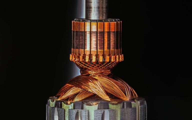
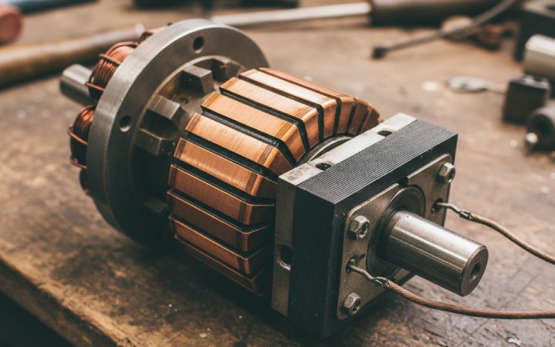
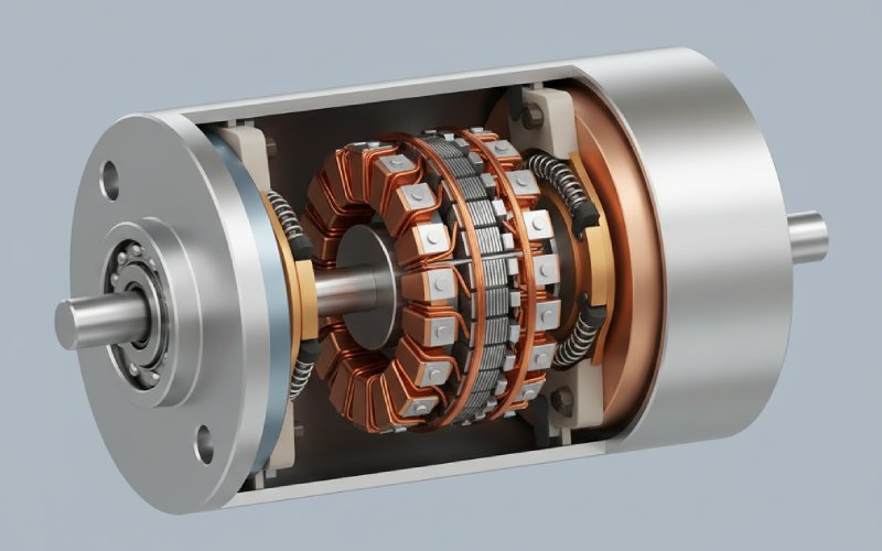
- Multi-segment commutator (multi-bar) A cylindrical stack of many copper bars, each isolated by mica or other insulation and tied to an armature winding system with many coils. Real DC motors and universal motors use this form, from a handful of segments up to hundreds in large machines.
Real brushed motors don’t stay with one loop and a two-segment ring for long. They add more windings; each loop gets its own pair of segments; torque becomes smoother; the machine stops stalling in the gaps.
That’s the essence of the difference.
2. Why industry almost never ships a pure two-segment split ring
The two-segment design is great for whiteboards and lab benches. In production it normally appears only where:
- torque is tiny
- speed is low
- duty cycle is small
- and failure just doesn’t matter much (toys, demo rigs, simple indicators).
Once you ask a motor to do real work, the limitations of the simple split-ring show up very fast:
- Huge torque ripple and dead spots With a single loop and two segments, the torque vs angle curve is ugly. There are rotor positions where the brushes sit on or near the insulation gaps and current collapses; the rotor can stall in those positions.
- Heavy arcing at the brushes Every time the brush switches that one loop, you dump the full stored magnetic energy of that winding across the gap as it opens. At speed, the result is strong arcing and noise at the brush/segment interface.
- Narrow safe operating window Voltage, current, and speed margins are thin. Slight overload → heat at the commutator, brush wear, copper smearing.
- Poor controllability Try running a pure two-segment design with PWM or tight speed control. It works in theory, but the ripple and commutation noise often cause more trouble than the motor is worth.
So, the market quietly transitions to multi-segment commutators for almost everything that isn’t disposable or purely educational.
3. What adding segments actually changes electrically
You don’t add segments just to make drawings more complex. Each extra segment reshapes the current paths and the commutation process.
A few key points, minus the textbook story:
- More segments → more coils → smaller current step per commutation Energy in each individual coil is lower, so each switching event at the brush is gentler. That directly reduces arcing and voltage spikes at the interface.
- Brush spans multiple segments In typical designs, a brush face intentionally covers roughly two to three segments at a time. That way, during commutation it briefly short-circuits a coil, letting the current decay before the coil is reconnected with reversed polarity.
- Commutation interval shrinks with segment pitch More segments → smaller mechanical angle per bar → shorter time between “old” and “new” connections. That helps at high speed but pushes manufacturing tolerances harder.
- Torque smooths out With multiple coils distributed around the rotor and tied to many segments, torque becomes closer to a DC level instead of a double-hump waveform. Anaheim’s own examples show how torque and speed regularity improve once the motor moves beyond a single loop and simple split ring.
So the real drive behind multi-segment commutators is simple: more stable torque, calmer commutation, higher usable speed and power.
4. Side-by-side comparison
From both engineering and purchasing viewpoints:
| Aspect | Simple split-ring commutator (2 segments) | Multi-segment commutator |
|---|---|---|
| Typical segment count | 2 | 6–40 in small motors, up to hundreds in large DC machines |
| Typical use | Educational motors, toys, very low-power devices | Tools, pumps, traction motors, drives, universal motors |
| Torque ripple | Very high; distinct “cogging” and dead spots | Much lower; more continuous torque profile |
| Start-up behaviour | Can stall on the gap if brushes land in the wrong place | Reliable self-start in almost any position |
| Max practical speed | Limited by severe arcing and heating at moderate RPM | Higher speeds possible; still limited by commutator mechanical strength and brush design |
| Voltage / power range | Very small machines, low voltage | Broad range from miniature motors to large DC generators |
| Brush wear | Concentrated on two copper faces; often uneven | Spread over many bars; wear more predictable with correct materials |
| Electrical noise (EMI) | Strong spikes per commutation event | More frequent but smaller events; easier to filter and design around |
| Manufacturing complexity | Simple ring, low tooling cost | Precise bar machining, insulation, pressing, turning, undercutting |
| Serviceability | Typically non-serviceable; entire motor replaced | Bars and mica can be re-machined or even replaced on larger machines |
| Unit price of motor | Lowest possible bill of materials | Higher part cost but usually lower cost per kWh delivered over life |
| Drawing complexity | Minimal detail | Needs specification of bar count, material, mica, undercut, balance, etc. |
The table hides one thing: risk. A poorly specified multi-segment commutator can cause more trouble than a crude but honest split ring. The rest of this article is about reducing that risk.
5. What engineers should check before choosing segment count
When you move from a simple split-ring concept to a multi-segment design, a few questions keep you out of trouble:
5.1 Load and duty cycle
- Short bursts, low inertia (e.g., small intermittent actuators) Medium segment counts are fine; commutation stress stays modest.
- Continuous duty, high inertia (fans, pumps, traction) You usually need more segments and a commutator sized for sustained current density in both bar and brush, not just peak torque.
Design notes from industrial practice highlight material, segment size, insulation quality, and surface finish as key drivers for efficiency and durability.
5.2 Speed range
Higher speed amplifies every commutation imperfection:
- brush bounce
- segment run-out
- imbalance in the copper/mica stack.
MIT’s DC machine notes stress that the commutator body is mechanically weaker than a solid steel rotor; overspeed events can become dangerous.
So, as speed goes up:
- segment count rises
- bar width and mica thickness shrink
- balance tolerances tighten.
5.3 Supply and control method
- Simple DC supply Less aggressive on commutation, but still sensitive to armature reaction at high load.
- PWM drives Faster edge rates stress the commutator. Segment geometry and materials have to accommodate higher dV/dt and resulting EMI.
- Reversible drives Any asymmetry in commutator geometry or brush alignment shows up immediately as different performance in forward vs reverse.
5.4 Environment
Dust, humidity, and chemicals all interact with copper bars and mica:
- Mica and resin systems must stay stable at the expected temperature and contamination level.
- For aggressive atmospheres, you’ll see different copper alloys and resin-rich insulation systems.
This is where simply saying “multi-segment commutator” in the spec isn’t enough. The details carry the life expectancy.
6. What purchasing should insist on for multi-segment commutators
If you’re buying motors or standalone commutators, your drawing and RFQ package should lock in more than just outer diameter and bar count.
6.1 Geometry and materials
Ask suppliers to confirm:
- Bar count and pitch (mechanical angle per segment)
- Bar material: e.g., electrolytic copper vs high-strength or silver-bearing grades
- Insulation: mica type and thickness range; resin or polymer system used between bars and to the hub
- Undercut: depth, width, and finish of the mica undercut between bars
- Method of retention: V-ring, glass-banded, internal or external steel shrink rings — each has different mechanical strength and cost.
These items show up repeatedly in industrial guidelines for commutator selection and refurbishment.
6.2 Tolerance and quality data
Reasonable minimums to request:
- Bar-to-bar resistance tolerance
- Total indicated run-out after final turning
- Maximum differential bar height after seasoning
- Dynamic balance grade of the rotor with commutator installed
- Hi-pot / insulation test results between bars and hub.
Your supplier may already have a standard set of values. Good ones do.
6.3 Brush / commutator pairing
The commutator isn’t a standalone part. It lives with a specific brush grade.
- Ask whether the commutator design assumes a given carbon grade or family.
- Check that current density in the brush and bar face is within the brush supplier’s recommended range.
This reduces the “black art” component and ties your motor life more explicitly to test data and known combinations.
7. Manufacturing and lifecycle contrasts
Even when both designs “work,” they age very differently.
7.1 Simple split-ring
- Typically molded or stamped as a single piece with two copper sectors and a basic insulating body.
- Often integrated into a very low-cost rotor assembly. When wear or pitting appear, the whole motor is scrapped.
Little point talking about re-machining; there’s nothing to remachine economically.
7.2 Multi-segment commutator
- Built from copper bars alternating with mica segments, pressed, banded, and mounted on an insulated hub.
- Mica segment thickness is controlled down to about 0.6–1.5 mm in many industrial designs, with tight tolerances to keep bar height uniform.
- Surface is turned and polished to a very smooth finish for stable brush contact.
On large machines, damaged bars and mica can be replaced or the surface can be re-turned and undercut; the commutator becomes a serviceable component rather than a disposable one.
So for long-life industrial systems, the extra up-front complexity is part of a maintenance strategy, not just a performance play.
8. Failure patterns: how the two designs misbehave
The failure modes you see in the field differ quite a bit.
8.1 Simple split-ring
- Heavy localized pitting on two copper faces.
- Rapid brush wear if the motor is overloaded.
- Frequent stalling at certain rotor angles, since torque collapses near the gaps.
Usually you don’t repair; you replace the whole motor.
8.2 Multi-segment
More varied, more interesting:
- Bar-edge burning and patterning when commutation is not centered in the neutral plane or segment pitch doesn’t match brush width well.
- Mica high (mica not undercut enough or copper worn faster), leading to brush bounce and sparking.
- Bar lift or banding failure from thermal cycling or overspeed.
The good news: most of these appear gradually and can be handled with scheduled maintenance if you designed and specified the commutator with service in mind.
9. Compact design checklist
If you’re moving a concept from a simple split-ring sketch to a commercial multi-segment motor, a short list helps:
- Decide torque ripple tolerance early From that, estimate how many active coils and commutator segments you need. Enough to keep torque variation, current ripple and EMI within spec.
- Size the commutator from current density, not convenience Start with brush and bar face current density limits, then back-calculate diameter and segment width.
- Align segment pitch and brush width Aim for a brush face spanning a little more than two segments so the short-circuit interval during commutation is controlled.
- Lock in insulation details on the drawing Mica type, thickness, and undercut geometry belong in the spec, not only in email.
- Ask suppliers for real measured data Bar-to-bar resistance, run-out, and balance numbers on sample parts give a quick view of whether the commutator process is under control.
Done right, a multi-segment commutator isn’t mysterious. It’s just a copper-and-mica component with tight mechanical and electrical discipline.
10. FAQ: Simple split-ring vs multi-segment commutators
1. Is a two-segment split-ring ever acceptable in production equipment?
Yes, but only in very low-power, low-consequence applications: toys, demonstrators, small mechanisms where stalling or wear is not critical. For anything with meaningful duty cycle, higher speed, or warranty expectations, a multi-segment DC commutator is almost always used.
2. Does a higher segment count always mean better performance?
Not automatically. More segments can smooth torque and reduce per-event commutation stress, but:
mechanical strength of the commutator falls as bars get thinner
manufacturing tolerances tighten
balancing becomes more demanding.
You want “enough” segments for your load and speed, not “as many as possible”.
3. Can I upgrade a motor from a simple split-ring to a multi-segment commutator without changing the armature?
Usually no. A proper multi-segment design assumes many coils distributed around the rotor, each tied to a pair of segments. Keeping a single loop and just cutting more copper bars into the ring doesn’t fix torque ripple or commutation; it just adds cost and complexity without the benefit.
4. How do commutator materials influence brush choice and life?
Softer copper grades and certain mica systems pair better with self-lubricating carbon brushes.
Harder copper alloys handle higher peripheral speed and mechanical abuse but can wear brushes faster.
Surface finish and cleanliness matter as much as composition; rough, dirty bars will destroy even a well-matched brush grade.
Good suppliers usually specify recommended brush families alongside the commutator design data.
5. What should I always ask a commutator supplier before placing a large order?
At minimum:
segment count, material, and insulation definition
machining tolerances on bar height and run-out
standard undercut dimensions
balance and test procedures on finished parts
recommended brush grades and current density limits.
If those answers are vague, the risk isn’t in the copper, it’s in your warranty budget.