Single Burned Commutator Segment: Causes, Diagnostics, and Repair Guide
Key Takeaways: A single burned commutator bar most often indicates a localized electrical fault (open coil, failed riser joint) or a mechanical anomaly (high bar, loose segment). However, broader commutation problems — brush holder alignment, interpole strength, spring pressure uniformity — must also be ruled out before concluding the fault is purely local. Diagnosis must precede any resurfacing. If the root cause is not corrected, the bar will burn again within days. When the burn exceeds the commutator’s minimum serviceable diameter, OEM-grade replacement is more reliable and often more economical than repeated repair attempts.
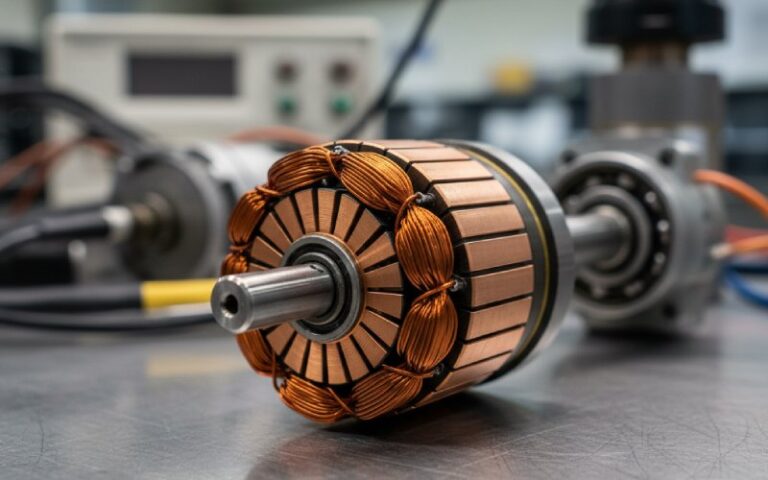
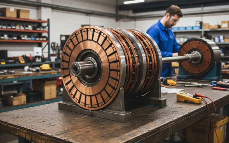
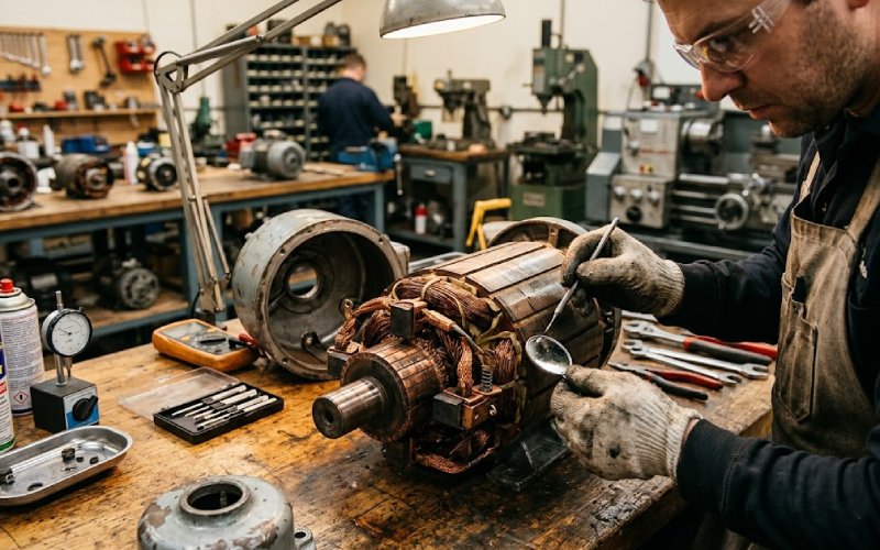
You pulled the end cover. One bar is black. The rest look fine — healthy tan-to-brown patina, no grooving, no threading. Just that one segment, cooked to charcoal. Maybe there’s a pit in the copper. Maybe the mica on either side is carbonized and bridging. The motor was sparking only at one specific rotational position, or the brushes were chattering once per revolution.
This is a single burned segment. And it behaves differently than general commutator wear — which means it demands a different diagnostic path and a different repair logic.
Table of Contents
Why One Segment Burns While the Others Survive
A uniform wear pattern — even a bad one — means the problem is systemic. Wrong brush grade, overload, contamination, out-of-round geometry. Those affect every bar roughly the same way.
A single bar burning? That’s most commonly local. The fault is usually traceable to one of these:
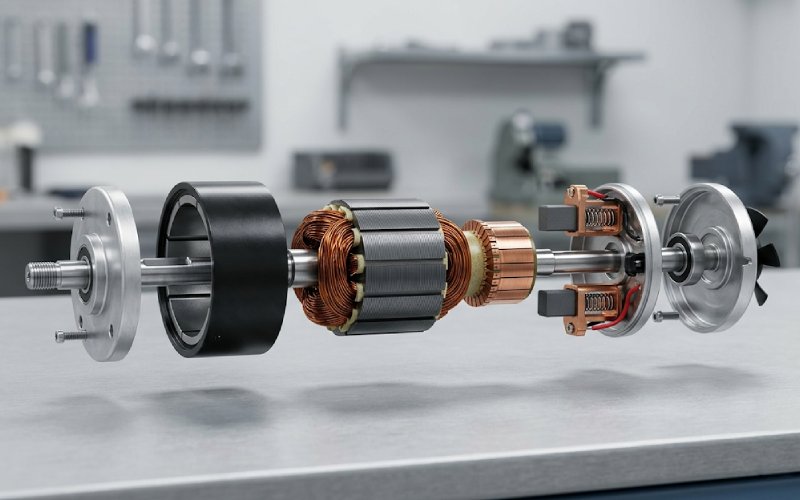
- Open coil. The winding connected to that commutator bar has broken — either at the riser (the connection tab where wire meets copper segment) or internally within the slot. When the brush sweeps across this bar, it can’t complete the commutation cycle. The stored inductive energy has nowhere to go. It arcs. It burns.
- Shorted turn. A partial short in the coil connected to that bar changes its impedance relative to its neighbors. Current redistribution follows. The affected bar runs hotter, draws more arc energy, and degrades faster than its neighbors.
- High bar. A mechanically raised segment — maybe 0.001–0.002″ higher than the rest — catches the brush on every pass. The brush bounces off the next bar, loses contact momentarily, and the re-contact arc is concentrated right there. Over time that one bar takes a beating.
- Loose bar. Thermal cycling or inadequate clamping force has allowed one segment to shift axially or radially. The disruption in the contact surface produces localized arcing.
- Riser joint failure. The solder or weld where the coil wire connects to the commutator riser cracks or goes resistive. The bar-to-bar resistance at that position jumps. Current still tries to commutate — but through a partially open connection, which produces heavy arcing confined to that spot.
In our production data, roughly nine out of ten single-bar burns we examine trace back to riser joint failures or open coils. The other causes show up, but less frequently.
One important caveat: Broader commutation problems can also manifest as localized burning on one or a few bars. Brush holders set off the neutral axis, incorrect interpole field strength, uneven spring tension across brush sets — these are system-level issues, but the resulting arcing can concentrate at specific angular positions on the commutator and produce what looks like a single-bar fault. Don’t close out your diagnosis until you’ve verified brush holder alignment and interpole function, even when the bar-level tests point to a clear local cause.
What You See on the Bench
Pull the armature and look. A single burned segment has a distinct appearance compared to general commutator distress:
| Feature | Single-Bar Burn | General Wear / Contamination |
|---|---|---|
| Burn pattern | One segment (sometimes two adjacent) blackened, pitted, or eroded | Uniform darkening, grooving, or streaking across all bars |
| Adjacent mica | Often carbonized or bridged on one or both sides of the burned bar | Mica condition relatively uniform (high, low, or adequate throughout) |
| Brush wear pattern | One brush may show a notch or localized chip from the bump | Even wear across the brush face, or groove matching the commutator profile |
| Commutator surface elsewhere | Healthy patina — tan, chocolate-brown, polished | May show threading, streaking, slot-bar marking, or general discoloration |
| Sparking behavior (reported) | Once-per-revolution flash at a fixed position | Continuous sparking at all brush positions or trailing sparks |
Bottom line: If you see one black bar surrounded by normal-looking copper, the most likely explanation is a local fault. Don’t treat it like a general resurfacing job. The bar is a symptom. The winding, the mechanical seat of that segment, or — less commonly — a system-level commutation problem is the disease.
⚠ Safety — Before You Touch Anything
DC motors store energy in ways that are not always obvious. Before any inspection, testing, or repair work:
- Lockout/Tagout (LOTO). Fully de-energize the motor and apply your personal LOTO lock and tag to the disconnect or breaker. Verify zero-energy state with a properly rated voltmeter before and after testing the meter on a known live source. This is not optional — it is a regulatory requirement in every jurisdiction we ship commutators to.
- Capacitor discharge. If the motor is driven by a DC drive or has associated capacitor banks, confirm that stored charge has been fully dissipated before approaching the terminals.
- PPE. Wear appropriate personal protective equipment: safety glasses at minimum during any mechanical work, insulated gloves rated for the circuit voltage during any electrical testing.
- Lathe safety. Do not wear gloves while operating the lathe or any rotating machinery. Gloves can be caught by the rotating workpiece or chuck and pull your hand in. Secure loose clothing, roll sleeves above the elbow, and remove rings, watches, and lanyards before approaching the machine.
- Megger/high-voltage testing. When performing insulation resistance tests at 250–500V DC, treat the commutator bars as energized until the test is complete and the megger has discharged. Keep hands off the bars during the test.
None of the procedures below should be performed by personnel who have not been trained and authorized for electrical work on DC rotating machinery.
Diagnostic Sequence — Finding the Actual Fault
Before you pick up a commutator stone or even think about the lathe, you need to identify why that bar burned. Resurfacing without answering this question is wasted effort — the burn will come back within days or weeks of putting the motor back in service.
Step 1: Visual Inspection
Examine the burned bar with a magnifier. Look for:
- Copper pitting deeper than the surrounding wear track
- Cracked or lifted riser connections
- Carbon bridging between the burned bar and its neighbors (this can create a bar-to-bar short and cascade the damage)
- Any sign of the bar being physically higher, lower, or shifted
Step 2: Bar-to-Bar Resistance
Use a low-ohms meter or, better, a millivolt drop test with a current-limited bench supply at 0.5–2 A. Measure between each pair of adjacent segments all the way around the commutator.
What you’re looking for:
- All readings within ~10% of each other = no obvious open or high-resistance connections detected at the risers. This result alone does not confirm the windings are fully healthy — shorted turns can hide behind normal-looking resistance values. Proceed to growler testing (Step 4) before concluding the coils are sound.
- One pair significantly higher than the rest = open or high-resistance coil connection, likely at the riser
- One pair significantly lower = shorted turn in that coil
- One pair reads open circuit = the coil is broken. Full stop.
Record every value. Number the segments with a marker first — it saves confusion later.
Step 3: Ground Test
Touch one probe to the shaft or lamination stack, the other to each bar in sequence. You should read open circuit (infinite resistance) on every bar. If the burned segment shows continuity to ground, the insulation in that coil has failed and the winding is grounded.
A megger at 250–500V DC gives a more definitive answer here than a standard multimeter on its high-ohms range. But a DMM will catch gross failures.
Step 4: Growler Test (If Available)
Place the armature on a growler and hold a thin steel strip (hacksaw blade works) over each slot. A shorted turn will cause the strip to vibrate and buzz over the affected slot. This test catches marginal shorts that simple resistance measurements might miss — it’s the step that turns Step 2’s screening result into a definitive verdict on winding health.
Not every shop has a growler, but if you’re doing volume DC motor work, the investment pays for itself quickly.
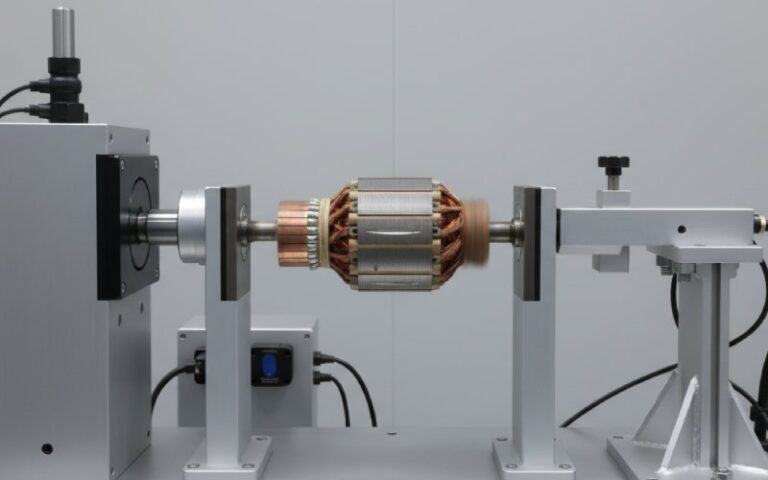
Step 5: Mechanical Check
Mount the armature between centers or on V-blocks. Run a dial indicator across the commutator surface. You’re checking:
- Total indicated runout (TIR). Anything above 0.002″ on the diameter warrants attention.
- Whether one bar sits higher or lower than its neighbors.
Tap each bar lightly with a small brass or plastic hammer. Tight bars produce a crisp, clear sound. A loose bar gives you a dull thud. You can feel the difference through the handle. Once you’ve been doing this for a while it becomes almost instinctive.
Step 6: System-Level Commutation Check
Even if Steps 1–5 point clearly to a local fault, take a few minutes to verify the broader commutation setup before reassembly:
- Brush holder position. Are the holders centered on the neutral axis? An off-neutral brush set concentrates arcing energy at specific commutator bars — and can masquerade as a local fault.
- Interpole field. On motors with commutating poles, verify the interpole air gap and winding integrity. Weak or asymmetric interpole fields cause uneven commutation across the bar surface.
- Spring pressure. Check every brush spring with a gauge. Uneven pressure across the brush set is one of the most common field-level causes of localized sparking — and it’s a system problem, not a bar problem.
If any of these are off, fixing the burned bar alone won’t prevent recurrence.
The Decision Matrix: Clean, Turn, or Replace
After diagnosis, you have three paths. Here’s how we make the call in our facility:
| Diagnosis | Burn Severity | Action |
|---|---|---|
| Mechanical high bar — coils test normal | Surface-level discoloration, no deep pitting | Light commutator stone, check mica undercut, balance if needed |
| Riser connection resistive but not open | Moderate burn, slight pitting | Re-solder the riser joint, machine the commutator, undercut mica |
| Open coil or fully broken riser | Deep pit, heavy carbon bridging | Replace commutator or rewind armature (depends on motor value) |
| Shorted turn confirmed on growler | Moderate to heavy burn | Rewind the affected coil (large motors) or replace the armature (small motors) |
| Loose bar confirmed | Varies | Tighten clamping ring/V-ring, re-machine commutator. If the bar cannot be re-seated, replace the commutator |
| Ground fault at burned bar | Any severity | Rewind or replace. A grounded armature is not repairable with surface work |
| System-level commutation issue identified | Varies | Address brush holder alignment / interpole / spring pressure before deciding whether the bar itself needs resurfacing or replacement |
The deciding factor is economics — but not just repair cost. Factor in the cost of a second failure. On a 200 HP mill motor, riser repair and commutator turning is a no-brainer — downtime and replacement lead times make repair the obvious choice. On a fractional-HP universal motor from a power tool? Buy a new armature. Maybe buy a new tool.
But here’s what we see too often: someone repairs a bar that should have been replaced, the motor fails again three weeks later, and now the unplanned downtime costs five to ten times what a new commutator would have. In our experience, when the repair cost exceeds roughly 60% of a precision-manufactured replacement commutator, replacement tends to provide better lifetime value — though your threshold may differ depending on motor criticality and lead time constraints.
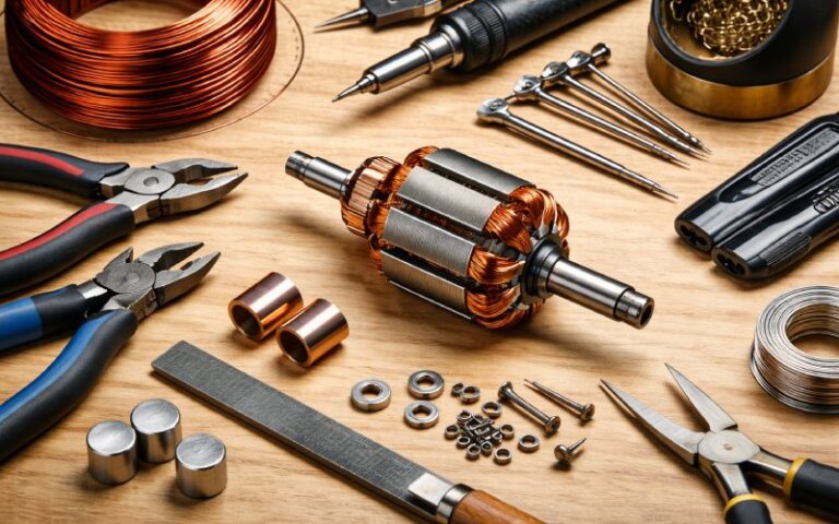
Tools and Equipment Required
Before beginning, confirm you have the following on hand:
| Tool / Equipment | Purpose |
|---|---|
| Digital low-ohms meter or millivolt drop tester | Bar-to-bar resistance testing |
| Megger (250–500V DC insulation tester) | Ground fault and insulation integrity testing |
| Growler (AC electromagnetic tester) | Detecting shorted turns |
| Dial indicator with magnetic base | Measuring commutator TIR and bar height |
| Commutator stone (medium grit) | Light surface cleanup |
| Lathe with carbide-tipped or diamond tooling | Commutator turning / resurfacing |
| Mica undercutting saw or hand tool | Recessing mica between bars |
| Chamfering tool or fine flat file | Deburring bar edges |
| Soldering iron (high thermal mass, 150W+) | Riser joint repair |
| Brass or plastic hammer | Tap-testing for loose bars |
| Brush spring tension gauge | Verifying even spring pressure across all brush holders |
| Vacuum cleaner (not compressed air) | Removing conductive carbon dust |
| Lint-free cloths and appropriate solvent | Final surface cleaning |
| Safety glasses, insulated gloves (for electrical testing) | PPE — no gloves during lathe work |
Repair Procedure for a Salvageable Single-Bar Burn
Assuming your diagnosis shows a recoverable fault — say a resistive riser connection or a high bar with sound windings — here’s the sequence we follow.
1. Clean the Commutator
Remove all carbon dust. Use a vacuum, not compressed air (air just redistributes the conductive dust into places you don’t want it). Wipe the commutator with a lint-free cloth dampened with an appropriate solvent. Make sure no threads or fibers catch between bars.
2. Address the Root Cause
- Resistive riser: Clean the joint with a fine file or abrasive. Re-solder with a proper soldering iron — you need enough thermal mass to get the joint to temperature without cold-soldering it. This is not delicate electronics work. The riser tab and the coil wire need to flow together solidly. Inspect under magnification after soldering.
- High bar: This will be corrected during the turning step. But check why it was high — a loose clamping ring, differential thermal expansion, or a shifted segment tells a bigger story.
- Mica bridging: Use an undercutting tool or a shaped hacksaw blade to remove the carbonized mica between the burned bar and its neighbors. Carbon-bridged mica creates a conductive path between segments and can re-burn the bar immediately after repair.
3. Turn the Commutator
Mount the armature between centers on a lathe. Take a very light cut — just enough to clean up the burned area and restore concentricity. Remove as little copper as possible. Each thousandth you take off shortens the remaining service life.
Surface finish: Target the finish specified by the motor OEM or the brush supplier’s recommendation. Common industrial ranges fall between 30–70 µin Ra, but the correct value depends on brush grade, current density, and operating speed. A surface that’s too smooth can be just as problematic as one that’s too rough — the carbon brush needs some texture to establish and maintain a stable copper-oxide film.
4. Undercut the Mica
After turning, the mica insulation between segments will be flush with or proud of the copper surface. It needs to sit 0.020–0.060″ below the bar surface (exact depth depends on the motor — larger machines generally take a deeper undercut).
Use a saw-type undercutter if you have one, or a hand tool with a blade shaped to the slot width. The cut should be flat-bottomed, centered in the slot, with no mica left riding against the copper edges.
5. Chamfer and Deburr
Break the sharp edges of each commutator bar with a fine file or chamfering tool. A 1/32″ to 1/16″ chamfer at 45° is typical. This reduces voltage stress at the segment edges and gives the brushes a smoother transition.
Remove all burrs. A copper sliver bridging from one bar to the next will cause an immediate short and potentially a flashover on startup.
6. Final Cleaning and Inspection
Vacuum all debris. Blow out the mica slots with low-pressure dry air if you must, then vacuum again. Inspect the entire commutator under good lighting. Run your fingernail across the surface — you should feel the mica slots clearly recessed but no raised edges or burrs.
7. Reassemble and Test
Re-install the armature. Seat the brushes properly — new brushes should be contoured to the commutator radius using a seating stone or fine abrasive strip. Verify spring tension is within spec (typically 4–6 psi for industrial applications, 6–8 psi for high-vibration environments) and, critically, uniform across all brush holders.
Run the motor at no load first. Watch the brush-commutator interface. You should see no sparking or only a very faint, uniform orange glow. Then apply load progressively. Monitor the area around the repaired bar specifically — any recurrence of localized sparking means the root cause wasn’t fully addressed.
When the Commutator Cannot Be Saved
Sometimes the burn is too deep. The copper at that bar is pitted below the minimum diameter. Or the growler confirms a dead coil. Or the bar is physically loose and the clamping structure is compromised.
At that point, surface work won’t save it. Your options are:
- New OEM-grade commutator assembly. This requires stripping the old commutator from the shaft, pressing on a precision-manufactured replacement built to the original segment count, bar dimensions, mica grade, and riser configuration, and then reconnecting every coil. On large industrial motors, this is standard repair-shop work. On small motors, it’s rarely cost-justified — but the commutator itself is often surprisingly affordable.
- Full armature rewind with new commutator. If the winding is also damaged — ground fault, multiple shorted turns, thermal degradation — you’re looking at a complete rebuild.
- Replacement armature. For fractional and small integral HP motors, a factory-built replacement armature is often cheaper and faster than bench work.
Here’s the reality from our quality control lab: We see motors come through where someone has tried to “touch up” a burned bar with a hand stone and put it back in service. It holds for a week. Maybe two. Then the same bar burns again, and this time it takes a neighbor with it, and now you’ve got a multi-bar failure that could have been a single-bar repair if it had been handled correctly the first time.
A precision-manufactured replacement commutator — built with Class F or Class H mica, silver-copper alloy bars, and machine-balanced to G2.5 or better — typically arrives within 5–7 business days from confirmed dimensions. In our experience manufacturing commutators for traction, industrial, and specialty DC motor applications, the total cost of a new commutator plus installation labor is frequently lower than the cost of a second unplanned downtime event caused by a failed repair.
Preventing Recurrence
A single-bar burn that’s properly diagnosed and repaired shouldn’t come back. But the operating conditions that contributed to the initial failure are still out there. Things worth checking before the motor goes back into service:
- Brush grade. Is the brush material matched to the operating current density and speed? Running too light a load with brushes designed for heavy current causes the copper-oxide film to deteriorate, which accelerates localized wear.
- Spring tension. Weak or uneven brush springs are the number-one field cause of localized sparking. Measure every spring with a gauge. Replace springs that have lost tension — they don’t recover. And check uniformity — one weak spring in a set of four can route excess current through the remaining three brush positions and overheat specific bars.
- Brush holder alignment and neutral axis. Confirm the brush holders are positioned on the geometric neutral. Off-neutral operation causes the commutation arc to be unevenly distributed across the bar surface, which can produce single-bar or localized-pattern burning that mimics a riser fault.
- Interpole health. On motors with commutating poles, verify that interpole air gaps are symmetric and that interpole windings are intact. A weak or shorted interpole shifts the commutation zone and concentrates arcing on specific bars.
- Environment. Abrasive dust eats commutators. Chemical contamination (chlorine, acid fumes, silicone vapors) attacks the protective copper-oxide film. If the motor operates in a harsh atmosphere, make sure ventilation and filtration are adequate.
- Drive settings. If the motor runs from a DC drive, overly aggressive acceleration or deceleration ramps can produce current spikes that stress individual commutator bars during commutation. Have the drive parameters reviewed if the burn coincided with a drive change or installation.
- Load profile. Frequent start-stop cycles or sudden load reversals are harder on commutators than steady-state running. If the application has changed since the motor was originally specified, the commutator may need more frequent inspection intervals.
FAQ
Can I just clean a burned commutator bar and keep running?
If the burn is purely surface discoloration — no pitting, no carbon bridging between segments, and the coils test normal on both resistance and growler — you can sometimes clean it with a commutator stone and get acceptable results. But if there’s any depth to the burn, or if the bar-to-bar resistance at that position deviates from the others, cleaning alone won’t fix it. You’re just polishing a symptom.
How do I know if the coil behind the burned bar is open or shorted?
Bar-to-bar resistance testing is your first screening tool. An open coil reads infinite (or very high) resistance between the adjacent bars connected to it. A shorted turn reads significantly lower than the average. However, resistance testing alone isn’t definitive for shorts — a growler test catches marginal shorted turns that resistance measurements can miss. If you find an open circuit, inspect the riser connection before assuming the coil itself is broken — a failed solder joint at the riser is far more common and far easier to fix.
Is one burned bar enough to cause a flashover?
On its own, usually not. But a burned bar with carbon bridging across the mica on either side effectively creates a wider conductive zone on the commutator surface. Under load — especially during transient conditions like startup or sudden load changes — that wider zone can be the initiation point for a flashover arc. It’s a low-probability event from a single bar, but the consequences are severe enough that it’s not worth gambling on.
Can I short two adjacent commutator segments together as a temporary fix?
In theory, on a motor with many segments, jumping one dead bar to its neighbor lets the healthy coil on the other side carry double the commutation arc. In practice, it creates an asymmetry that unbalances the magnetic field, increases vibration, and puts extra thermal stress on the coils that are now doing double duty. On a 20+ segment commutator running a non-critical load, it might get you through a shift. It’s not a repair. And it’s not something we’d recommend for anything you plan to keep running.
How much copper can I remove when turning a burned commutator?
Only enough to restore concentricity and clean up the burn. Most commutators have a minimum diameter specification — typically stamped on the clamping ring or documented in the motor’s service records. If the burn has pitted below that minimum on even one bar, the commutator needs replacement rather than turning. As a general rule, we plan each cut to remove no more than 0.005–0.010″ on the radius per service, knowing that we may need 3–5 resurfacings over the motor’s life.
What brush grade helps prevent localized burning?
There’s no universal answer — it depends on current density, surface speed, ambient conditions, and the motor’s commutation characteristics. But the most common mistake we see is running a standard electrographite brush on a motor that’s lightly loaded. The current density drops too low to maintain the protective copper-oxide film, and the commutator surface deteriorates unevenly. If your application operates below 50% of nameplate load for extended periods, talk to your brush supplier about a grade with wider current-density tolerance.
When does it make more sense to replace the commutator than to repair it?
In our experience, when the repair cost exceeds roughly 60% of a new precision-manufactured commutator matched to your exact specifications, replacement tends to provide better lifetime value — but your break-even point will depend on motor criticality, acceptable downtime risk, and how many resurfacing cycles the existing commutator has already consumed. If you’re approaching the minimum diameter, another cut buys you months, not years. A new commutator resets the clock entirely.
Could my single-bar burn actually be a system-level problem, not a bar-level problem?
Yes. Brush holders set off the neutral axis, a weak or shorted interpole, or uneven spring pressure can all concentrate arcing on specific commutator bars. The resulting burn pattern can look identical to a riser failure or open coil. This is why the diagnostic sequence includes a system-level commutation check (Step 6) even after local tests come back clean. If you fix the bar but the brush holders are 5° off neutral, you’ll be pulling that motor apart again soon.
Need a replacement commutator matched to your exact armature dimensions? Our engineering team builds OEM-grade commutator assemblies for traction, industrial, and specialty DC motors — typically quoted within 24 hours from your nameplate data or dimensional drawing. [Contact us →]