Designing Commutator Assemblies That Don’t Fail in the Real World
When the commutator assembly is right, the motor behaves like a quiet piece of infrastructure and everyone ignores it. When it is off by a little, you get brush dust everywhere, strange trips, and a maintenance log that never quite closes. This article is about building and keeping the kind of assembly that people forget about.
Table of Contents
What the commutator assembly really has to do
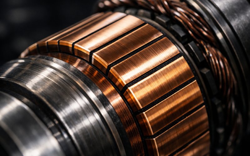
You already know the textbook description. In practice, the commutator assembly has a simpler job: keep current reversal predictable while surviving mechanical abuse, thermal cycling, and dirty air. If those three things hold, torque stays smooth and brush wear looks boring. Research on traction motors shows that once commutation quality degrades, arc duration spikes and reliability falls in a very non-linear way, so “almost fine” is usually not fine at all.
That is why most high-duty motors treat the brush–commutator unit as a single system. Copper, mica, brush grade, spring gear, housing stiffness, bearings, even cooling air all sit in the same bucket. Modern reliability studies model the unit as one block and use it to predict brush wear, probability of failure-free operation, and remaining life. If you assemble the commutator as if it is a standalone part instead of part of that system, you end up chasing symptoms later.
Design choices that show up later on the shop floor
Design decisions feel abstract on paper, but assembly teams live with them for years. Diameter is a good example. Current density at the brush face tends to dominate the choice, but the surface speed limit at full rpm and the physical space for your brush gear quietly restrict the useful range. If the diameter is too small for the current, the machine might pass type tests yet still run with chronic micro-arcs and high dust.
Segment count follows the same pattern. More segments mean smoother commutation and smaller bar-to-bar voltage, but every bar you add gives you another braze joint, another chance for looseness, another inspection item for the next decade. Design notes often talk about electrical optimization, while field failures are usually mechanical or thermal. Service failure analyses regularly trace issues like bar burning, threading, and copper drag back to loosened segments or poor support, not to wrong equations.
Mica height and undercut depth are also worth deciding with assembly in mind. Too shallow and undercut cleaning becomes a ritual that never ends. Too deep and brush edges start chipping, especially when spring pressure is already conservative. Carbon brush guides warn that incorrect spring tension is still one of the most common root causes of brush issues, so giving the brush a forgiving surface profile matters more than a perfect drawing.
A practical assembly sequence that avoids hidden stress
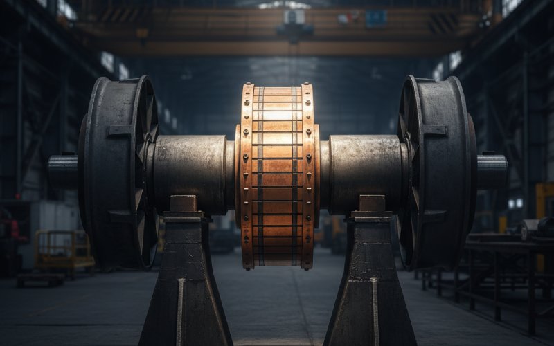
Most factories follow a version of the same path: fabricate copper segments, insert mica or other insulation, clamp the stack around the hub, mold or band the outside, attach risers, then machine and undercut. The trouble is not the sequence itself. The trouble is where stress gets locked in without anyone noticing.
When the copper stack is pressed on the hub, residual hoop stress is your silent variable. A press that is slightly off-center, a taper that was not cleaned, or a temperature difference between stack and hub can leave you with non-uniform contact pressure. The assembly passes immediate checks, but after a year at load, a few bars start to rock. Those become the bright segments that show up in maintenance guides as “local high” or “bar marking.”
During riser brazing or welding, you are chasing a different trade-off: enough heat to give reliable joints without pulling segments out of alignment. Local overheating can soften copper, distort the stack, and preload certain bars against the brushes. Unless you record bar-to-bar resistance and insulation values at this stage, you end up discovering the issue only after machining, when fixing it is much more expensive.
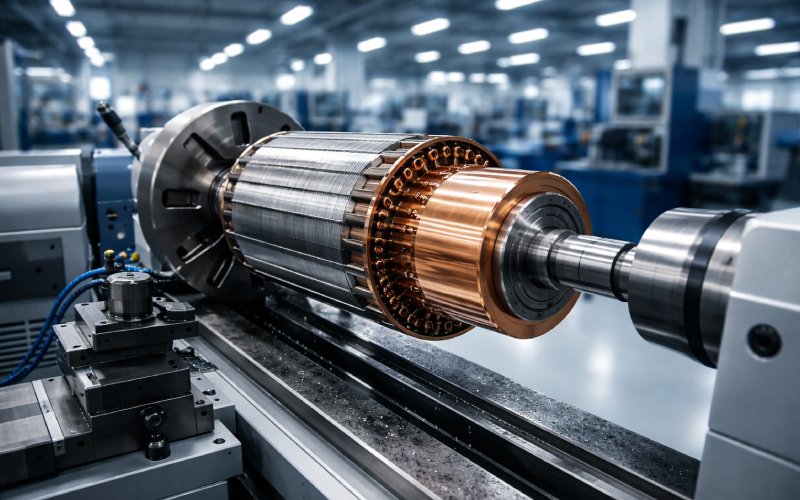
Machining and undercutting form their own small world. The best practice manuals still recommend proper machining in a lathe or grinder rather than aggressive in-place resurfacing, except when access is impossible. Here, your goal is not a pretty finish but a surface film that will form correctly under real brushes, humidity, and current. The geometry and roughness set the starting condition; the film does the rest.
Dynamic balancing and initial brush run-in are where the assembly stops being a stack of parts and becomes part of a machine. Some manufacturers include a short controlled run under load in clean air specifically to build a stable film before the unit ever sees service. Hydrogenerator guides emphasize that film condition, not just geometry, controls long-term performance and spark behavior.
Assembly checks that actually change reliability
The table below collects a set of checks that show up across standards, maintenance guides, and reliability studies. It is not exhaustive, but if you get these consistently right, the odds of serious commutator trouble drop a lot.
| Checkpoint | What you really inspect | Typical target or habit (not a spec) | Failure signal that points back to assembly |
| Commutator TIR vs. shaft | Total indicated runout after final machining and after several heat cycles | On the order of a few hundredths of a millimeter on medium machines | Localized sparking, bar burning on every revolution, brush bounce |
| Bar tightness | Mechanical movement between bars under light tapping or bar-to-bar tests | No relative movement; uniform bar-to-bar readings | Copper drag, lifted bars, random flashovers |
| Insulation integrity (bar-to-bar and to hub) | Insulation resistance and dielectric strength after brazing and molding | High and uniform IR; no partial discharge at test voltage | Tracking, mica breakdown, recurring arcing at same zones |
| Mica undercut | Depth and cleanliness relative to bar face | Slightly below copper surface, edges clean and smooth | Threading, heavy copper burrs, chipping of brush edges |
| Brush spring pressure | Actual force at operating position, not catalog value | Within supplier’s recommended window for grade and size | Rapid brush wear, streaky film, “ghost” marks on certain bars |
| Surface finish and film readiness | Roughness after machining and stone polish, absence of smeared copper | Fine turned or ground, no torn metal, no heavy ridges | Patchy film, hot spots, early ridging |
| Brush alignment and contact area | Contact pattern after run-in, alignment of boxes to the neutral plane | Contact band centered, at least 80–90% area after run-in | Uneven wear, asymmetrical sparking, high current density on edges |
| Ventilation paths around assembly | Clearance for air, dust collection, access for inspection | Clear ducts, cable routing that does not trap dust | Blackened housing, insulation fouling, carbon tracking across surfaces |
These checks do not replace standards, but they express the way experienced technicians actually talk about a “good” assembly. They connect drawings to how the unit ages.
Failure patterns that point straight back to assembly
When a machine arrives with commutator trouble, the wear pattern usually tells you whether you are dealing with a design issue, an operating issue, or a pure assembly mistake. Documents on failure modes describe a predictable set of surface conditions: light bonded film and blotchy but smooth surfaces are usually acceptable, while streaking, bar burning, threading, and copper drag are red flags.
Threading often suggests that the undercut and surface finish never gave the brushes a fair chance. The brush was skidding instead of sliding, gradually carving helical marks. Copper drag and lifted bars tend to trace back to poor bar support, weak bonding, or distortion during brazing or shrink-fit. Those problems start in assembly long before the motor sees any overload.
Flashovers are more complex. FMEA studies on DC machines point to a combination of causes: insulation degradation, incorrect brush setting, wrong grade, and mechanical defects. But when the same few bars are always at the center of the burn pattern, it is usually structural. Either those bars are higher, looser, or sitting on poor insulation. In that case, changing brush grade or tweaking the interpoles only masks the root cause.
There is also the quiet failure mode where everything looks acceptable to the naked eye, yet brush life is much shorter than expected. Reliability work on traction motors links that behavior to small increases in arc duration at the brush–commutator interface, usually from minor geometric or thermal imbalances.This is where better assembly records and more detailed tests pay off.
Bringing diagnostics closer to the assembly line
Most plants still treat advanced diagnostics as something you do later, when the machine is installed. That is an odd habit. If you already have access to the armature, commutator, and brush gear on the bench, this is the easiest point to build a baseline.
A practical approach is to pair traditional checks with at least one quantitative signal linked to future reliability. For example, some traction motor studies use sensors and high-speed monitoring to measure arc duration per brush at different loads and speeds. Production testing does not need to be that fancy, but even a simple measurement of vibration and current noise under a controlled brush load can separate truly good assemblies from merely acceptable ones.
The other piece is structured feedback. Maintenance standards and railway guides already recommend systematic logs for commutator and brush-gear inspections, including brush length, film condition, spring pressure, and surface defects. If you link those logs back to individual assembly batches, you can build your own informal reliability model without waiting for a published paper. Over a few years, patterns emerge: a certain supplier, a specific brazing fixture, or a particular operator consistently produces units with longer brush life or fewer flashovers. That information is much more valuable than another generic maintenance checklist.
Practical guardrails for teams building commutator assemblies
If you want your commutator assemblies to stop showing up in failure reports, a few habits matter more than any slogan. Treat the brush–commutator system as a single unit and keep its geometry, materials, and cooling consistent from design through assembly. Record more than just pass/fail numbers during pressing, brazing, machining, and balancing, and make those records searchable by serial number so field issues can be traced back quickly.
Give the surface film a chance by controlling machining, cleaning, and first run conditions instead of leaving them to chance. Maintenance guides remain very clear on this: dust control, correct spring force, and regular inspection of surface condition prevent a surprising amount of trouble.
Finally, close the loop. Every time a commutator comes back with bar burning, loose segments, abnormal wear, or repeated arcing, treat it as feedback on the original assembly, not just as a maintenance job. Over time, your drawings will change a little, your process sheets will change a lot, and your commutator assemblies will quietly stop being the weak link in the motor. That is the point.