Purpose of a Commutator in a DC Motor
Table of Contents
1. Short technical refresher
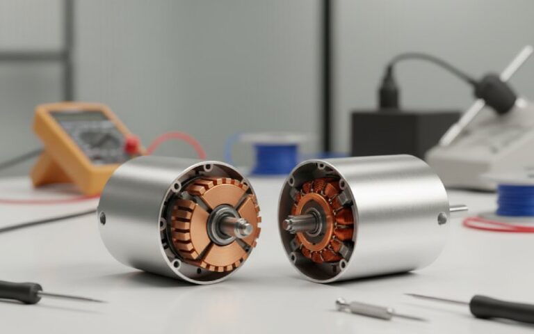
In a brushed DC motor:
- The armature windings sit on the rotor.
- The commutator is a segmented copper cylinder tied to those windings.
- Brushes sit on the commutator and feed DC from the stationary side.
As the rotor turns, the commutator periodically swaps which segment each brush touches, which flips the current in the active armature coils every half mechanical revolution and keeps the developed torque roughly in one direction.
That’s the basic purpose. But in real projects, the commutator ends up doing more work than the simple one-line description suggests.
2. The real purposes of a commutator in a DC motor
Think of the commutator as five things at once.
2.1 Maintain unidirectional torque from a DC supply
Yes, the obvious one, but notice the nuance:
- Inside the rotor, coil currents are alternating in each slot as the machine turns.
- At the terminals, you still present a DC motor to the user: reasonably constant shaft torque and a DC current profile (ignoring ripple).
So the first purpose is functional conversion:
From: DC supply with fixed polarity To: Armature coil currents that flip polarity in sync with rotor position.
This is why a commutator belongs to DC motors and generators, while slip rings sit in AC machines that don’t need this switching action.
2.2 Provide a controlled current path through a messy armature
A modern DC motor armature is not just “one loop and two segments”. It’s:
- Many coils,
- Distributed in slots,
- Connected in a lap or wave winding pattern.
The commutator’s second purpose is to organize current paths so that:
- As many conductors as possible contribute to developed torque at any instant.
- Torque ripple stays within the level your application can tolerate.
- Brush current per path stays within thermal and wear limits.
From a B2B angle: number of segments, wiring scheme, and brush arrangement directly influence:
- Torque smoothness,
- Speed range where commutation remains acceptable,
- Size of suppression components you need in the drive electronics.
2.3 Act as a sacrificial, maintainable interface between rotor and stator
The brushes + commutator pair is designed to wear. By intention.
The third purpose is to concentrate mechanical wear and arc erosion on parts you can resurface or replace, instead of on the rotor core or external wiring.
Tribology studies on brush–commutator systems show that these surfaces develop complex “tribolayers” that balance electrical contact, lubrication, and wear debris.
This matters because:
- In a plant, replacing brushes and skimming a commutator is routine.
- Rewinding a rotor or scrapping a motor is not.
So the commutator’s purpose extends into maintainability and life-cycle cost, not just electromagnetic function.
2.4 Shape commutation quality: arcs, EMI, noise, reliability
During each segment transition, current tries to keep flowing in the coil (inductance doesn’t change its mind instantly). If the brush leaves a segment too quickly or the coil is under heavy load, you get:
- Sparking at the brush,
- Carbon dust,
- Local heating and surface damage,
- Electrical noise that radiates into your control system.
So the fourth purpose of the commutator, in a more practical sense:
To keep that unavoidable switching event inside acceptable limits for wear, heat, and EMC.
Geometry, materials, and brush position all exist to manage the severity of the switching event. A “cheap” commutator doesn’t just fail mechanically; it forces the rest of your system to work harder.
2.5 Provide a tuning knob for performance vs cost
Because so many performance variables funnel through the commutator, it becomes a quiet negotiating space:
- Need long life and steady torque at low speed? → More segments, better surface finish, specific brush grades.
- Need a compact, low-cost drive for intermittent duty? → Fewer segments, simpler machining, more basic materials.
So one more purpose, rarely written in textbooks:
The commutator gives designers and buyers a practical way to trade cost against life, noise, and performance without changing the fundamental DC motor principle.
3. Summary table: what the commutator does vs what that means for you
| # | Purpose in the DC motor | What actually happens | What it means in a B2B project |
|---|---|---|---|
| 1 | Maintain unidirectional torque | Current in active coils flips polarity every half turn while supply remains DC. | Predictable torque direction, simple control, easy integration with legacy DC drives. |
| 2 | Manage current paths | Segmented cylinder and winding pattern distribute current among many coils. | Lower torque ripple, narrower commutation “hot spots”, smaller brushes for a given output. |
| 3 | Provide a sacrificial interface | Brushes and segments wear, form tribolayers, and can be resurfaced or replaced. | Planned maintenance items instead of sudden rotor failures; predictable spare-parts planning. |
| 4 | Control commutation stress | Segment geometry and brush lead angle limit arcs and overvoltage at each switch. | Less sparking, fewer nuisance trips, less EMI filtering in the drive cabinet. |
| 5 | Offer design tuning | Segment count, materials, and finish tuned for duty cycle and budget. | You can align motor price with real-world usage instead of over-specifying everything. |
Use this table as a checklist when you compare suppliers. If a proposal ignores these points and just quotes rated power and speed, you know roughly how much thought went into the commutator.
4. Design choices that change how well the commutator achieves its purpose
You already know the basic “more segments = smoother commutation” idea. Real projects push a bit harder on the details.
4.1 Segment count and proportioning
Segment count is constrained by:
- Minimum mechanical width for robustness,
- Required creepage distances,
- Brush width and number of brush arms.
Key ideas for practice:
- Higher segment count → Finer granularity of switching, smoother torque, but more complex machining and potentially more issues if alignment is poor.
- Lower segment count → Cheaper, but each switching event is “bigger” electrically; watch sparking at higher speeds or loads.
For high-speed machines, unequal segment wear and eccentricity show up quickly if the commutator is not precisely turned and balanced.
4.2 Brush material vs commutator purpose
Brush grade interacts strongly with the commutator’s purpose as a sacrificial interface and as an internal switch.
Typical trade-offs (simplified):
- Carbon-graphite brushes
- Lower friction, reasonable life.
- Good for general industrial DC motors.
- Copper-graphite brushes
- Lower resistance, higher current density.
- More aggressive on the commutator surface; watch for faster wear and need for better cooling.
- Special alloyed brushes
- Tailored for very low voltage drop, or extremely high switching frequency, or specific contaminant conditions.
Choosing brush grade is not only about current; it is also about how cleanly the commutator carries out its switching purpose without extreme arcing or rapid wear.
4.3 Brush position and interpoles
Factories still adjust brush position by trial and error when replacing motors or rewinding armatures.
- Moving brushes slightly forward or backward relative to the neutral plane changes where in the coil’s current waveform the switching occurs.
- Interpoles (commutating poles) add a local magnetic field to assist current reversal during commutation.
So another layer of purpose appears: the commutator is part of a team with field geometry and interpoles to keep current reversal under control across the full load range.
If you specify a motor for wide load variation and bidirectional operation, check that the supplier explains how brush setting and interpole design support that.
4.4 Surface finish, concentricity, and cooling
Once the motor leaves design and moves into production:
- Poor surface finish → erratic contact, hot spots, extra sparking.
- Out-of-round commutator → brushes bounce, arcs stretch, contact pressure varies.
- Weak cooling → local copper temperature rises, mica softening risk, faster wear of both brushes and segments.
So the commutator’s purpose includes “being a stable mechanical platform for sliding contact”, not just a circuit element.
5. Where commutators sit vs slip rings and brushless designs
A fair question in 2026: if brushless motors are everywhere, why are you still buying commutated DC motors?
Because the commutator’s purpose is different from a slip ring and different again from an electronic inverter.
5.1 Commutator vs slip rings (quick contrast for sourcing decisions)
Slip rings:
- Provide continuous electrical connection between stationary and rotating parts.
- Do not intentionally reverse current; they simply carry whatever waveform is supplied (often AC).
Commutators:
- Provide connection and controlled reversal tied to mechanical position in the motor.
- Turn internal AC-like coil behavior into externally-seen DC behavior.
For a buyer, the core question is:
“Do I want the switching action built into the rotor (commutator) or moved out to power electronics (brushless + inverter)?”
Both approaches can solve the same mechanical task, but the cost, maintenance pattern, and supplier ecosystem will differ.
5.2 When a commutator still makes sense
Typical cases where the commutator still earns its place:
- Brownfield plants with existing DC drives and service practices.
- Applications where the motor is cheap, the electronics must stay simple, and maintenance staff already know how to inspect brushes.
- Harsh environments where closely-packed electronics would struggle, but robust copper and graphite can be maintained.
In those cases, the purpose of the commutator in a DC motor isn’t just electrical; it is organizational:
It keeps complexity inside a mechanical assembly that your team already knows how to replace.
6. Maintenance and monitoring: when the commutator stops doing its job
If the commutator fails at its purpose, it often announces itself loudly.
Typical symptoms:
- Heavy sparking around the brushes, sometimes all the way around the commutator, pointing to shorted turns or inter-segment shorts.
- Patchy discoloration or ridging on the copper surface.
- Uneven brush wear, with some arms running hotter than others.
- Noise in nearby control wiring, nuisance trips of drives or protection relays.
Common underlying issues:
- Short circuits in armature windings or between commutator segments.
- Incorrect brush position after maintenance.
- Wrong brush material for the duty cycle.
- Contamination (abrasive dust, oil, moisture) disrupting the tribolayer on the surface.
When you see these, it is not just a “fault”; it is a sign that the commutator is no longer achieving its designed roles from sections 2 and 3.
7. Buying and specification checklist: use the purpose, not just the rating plate
When you next write a spec or compare quotes for DC motors or spare armatures, you can turn the commutator’s purposes into direct questions:
- Torque and commutation
- At what speed and load does the manufacturer rate commutation as “clean” without excessive sparking?
- How many commutator segments, and how does that tie to torque ripple requirements?
- Wear and service
- What is the expected brush life and commutator resurfacing interval under your duty cycle?
- Are there recommended brush grades for your environment (humidity, dust, voltage level)?
- Noise and EMC
- Any data or guidelines on conducted and radiated noise vs speed and load?
- Suggested filtering or wiring practices for your system layout?
- Field flexibility
- Are brush holders adjustable, and is the correct neutral position clearly marked?
- For reversible operation, how is commutation supported in both directions?
- Spare-parts strategy
- Are commutators and brush gear supplied as individual parts, or only as full rotor assemblies?
- Can your local service partner reskim commutators to the manufacturer’s tolerances?
If a supplier can answer these without guessing, it’s a sign that the purpose of the commutator has been thought through beyond the catalog drawing.
8. FAQ: Purpose of a commutator in a DC motor
Q1. Is a commutator always required in a DC motor?
Not in every design that carries a DC label. Some so-called “DC” drives are actually electronically commutated (brushless DC motors) and use semiconductor switches plus position feedback instead of a mechanical commutator. In traditional brushed DC motors, though, the commutator is essential because it performs the current reversal tied to rotor position.
Q2. Why can’t I use slip rings instead of a commutator in a DC motor?
Slip rings only pass current; they do not control its direction. In a DC motor you need current in the active coils to flip relative to the field to maintain a roughly constant torque direction. That directional control is exactly what the commutator provides, which slip rings cannot.
Q3. What is the main purpose of the commutator for a plant engineer?
Practically: to keep torque smooth enough, noise low enough, and maintenance predictable enough that the motor behaves like a reliable black box. The engineer does not directly interact with individual coils; they interact with the commutator and brush gear during inspections and overhauls.
Q4. How does commutator design affect maintenance cost?
More segments, better materials, and correct brush selection usually produce cleaner commutation and slower wear, at higher upfront cost. Poor design or mismatched brushes lead to more frequent resurfacing, carbon dust, higher temperatures, and shorter motor life, which shows up later in unplanned downtime and service bills.
Q5. When should I move away from commutated DC motors?
Consider a move to brushless or AC machines when:
1. Maintenance access is very limited or expensive (e.g., offshore, remote sites).
2. EMC limits are tight and arc noise is a concern.
3. Speed range and dynamic performance requirements are high enough that mechanical commutation becomes the bottleneck.
Where legacy systems, simplicity, or harsh mechanical conditions dominate, a commutator still does its job well.