Purpose of a Split Ring Commutator (the “split” is not the point)
Most pages stop at: “it reverses current every half turn.” True. Thin.
The split ring commutator exists to keep the outside world “DC-ish” while the rotating armature does its alternating thing. In a motor, that means torque doesn’t flip sign. In a generator, it behaves like a mechanical rectifier: alternating armature EMF becomes one-way current at the brushes.
That’s the purpose. The rest is how you keep it from eating itself.
Table of Contents
The real job: timed reconnection, not “reversal”
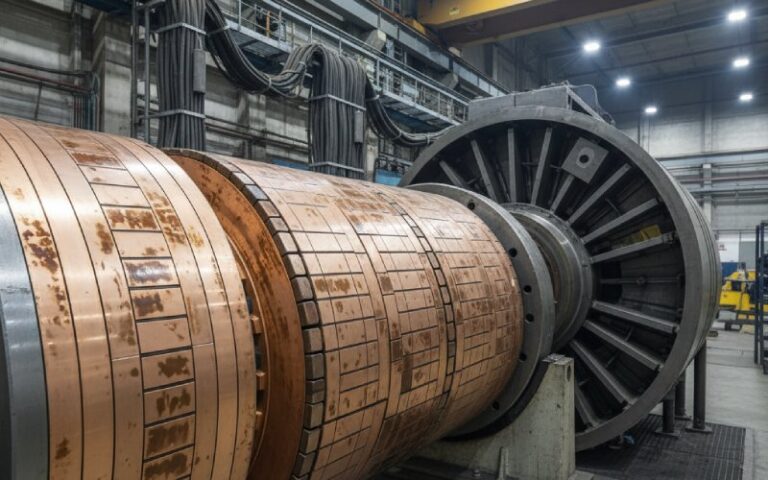
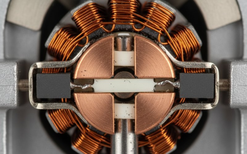
In the demo-motor version, the split ring swaps a single coil at the dead zone. Real machines scale it: segmented cylinder, multiple coils, brushes bridging bars.
And here’s the part that matters.
During commutation, a coil is briefly shorted by the brush spanning adjacent segments. Current must decay, hit zero, then build opposite. Not instantly. It tries. It fails.
Because armature coils are inductive, forcing that current change too fast creates an inductive kickback (a voltage spike). That spike shows up right where you don’t want it: brush edge → air gap → arc. Copper loss, carbon tracking, heat marks, more arc. Loop.
So “purpose” includes a second clause people skip: switch coils at the right moment, while keeping inductive arcing within limits.
What you get (Motor vs. Generator), with the buyer reality included
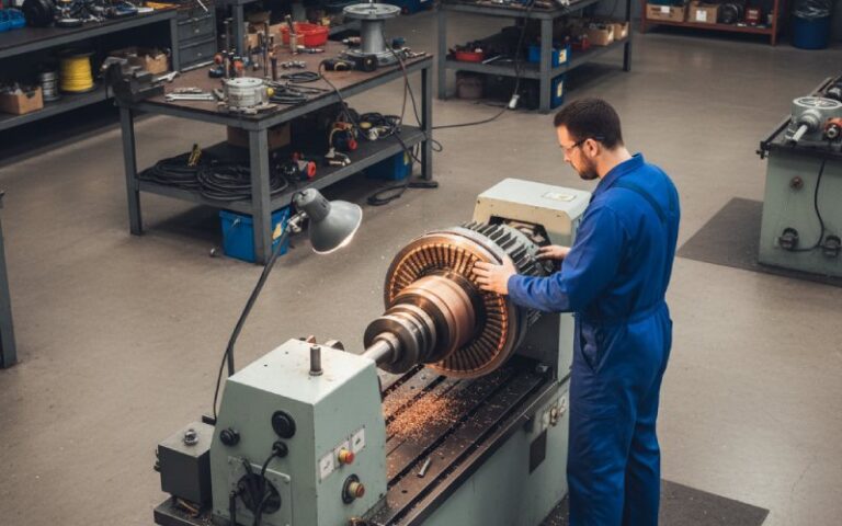
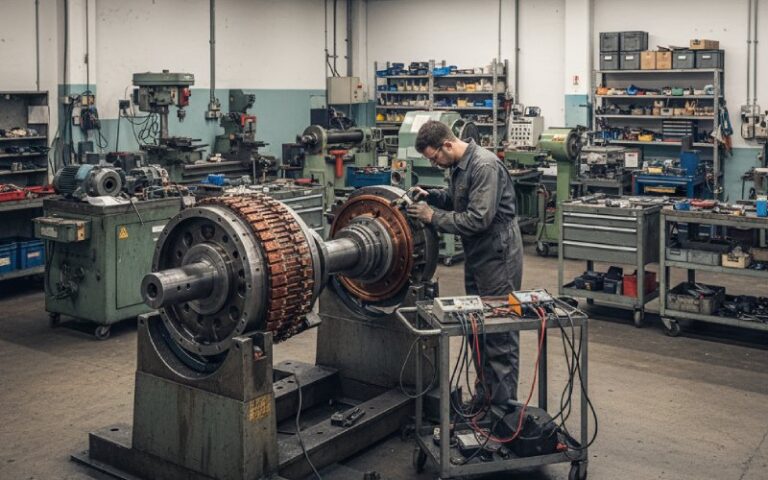
For buyers, this is less a “component” and more a wear interface that quietly sets the maintenance interval for the whole machine.
In DC motors
- Unidirectional torque from a rotating armature because coil connections are flipped relative to the field at the right rotor position.
- A practical way to feed current into a rotor without flexible leads. You pay in brushes.
In DC generators (dynamos)
- Unidirectional terminal polarity because the commutator flips coil connections each half turn, presenting rectified output at the brushes.
Same family. Different direction of power flow. Same brush line.
The cost of that purpose: the brush track becomes the system
If you run commutators in production equipment, you already have the list. Film. Mica. Runout. Brush grade. Dust. Humidity. Spring pressure drift.
A few items that actually show up on work orders:
- Sparking isn’t cosmetic. Poor commutation control turns into track damage, segment edge erosion, brush wear acceleration.
- High mica / poor undercut / burrs: they don’t just look bad. They change contact, then you chase sparks with brush pressure, then you chase heat.
- The surface film is doing work. Too glossy is a problem. Too raw is a problem. Both happen.
Table: purpose → mechanism → what you inspect
| What people say the purpose is | What’s happening physically | What you inspect / control in practice |
|---|---|---|
| “Reverse current every half turn” | Coil is shorted under the brush; current must reverse without an inductive spike becoming an arc | Neutral plane/brush position, sparking pattern, segment edge condition, interpole/compensation setup (if present) |
| “Keep torque in one direction” | Switching keeps armature force direction consistent instead of oscillating | Brush position shift vs load, bar heating, brush grade fit, commutator runout |
| “Convert armature AC to DC (generator)” | Mechanical rectification via segment timing | Segment insulation condition, slot cleanliness, film stability, brush contact uniformity |
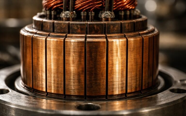
| “Provide a rotating electrical interface” | Sliding contact transfers current and also becomes a wear component | Surface roughness, mica undercut/chamfer, spring pressure consistency |
If a competitor’s article never mentions shorted coils under the brush, it’s not really about purpose. It’s about passing an exam.
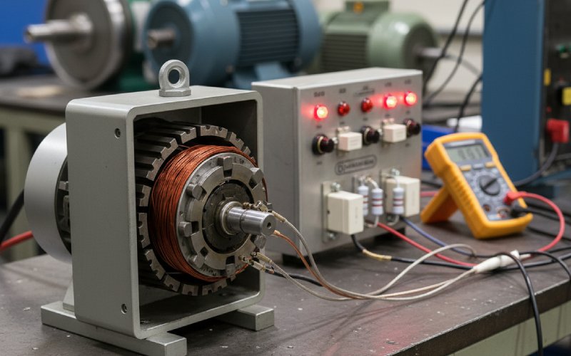
Spec’ing a split ring commutator (the bits that decide whether it behaves)
Not a full datasheet. Just the parts that keep coming back.
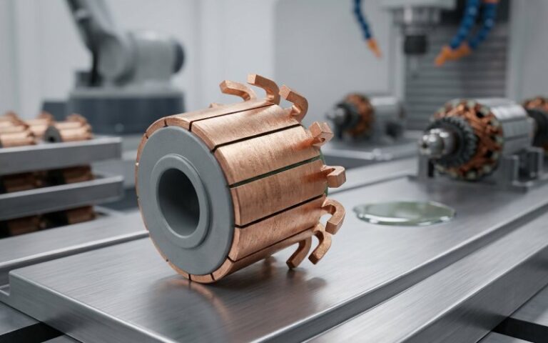
- Segment count & geometry: more segments usually smooths commutation, but increases insulation lines and sensitivity to contamination.
- Insulation system & undercut quality: undercut depth consistency, clean slots, no burrs. The boring stuff. It’s not boring later.
- Brush system pairing: brush material + film behavior + current density. A package, not three independent choices.
- Spring pressure: supplier guides often give starting ranges (e.g., ~180–250 g/cm² stationary machines, ~350–500 g/cm² high-vibration traction-type service). Useful as a baseline. Actual pressure depends on speed, vibration, current density, and brush grade. If you ignore that, the “range” becomes a trap.
- Environment: oil mist, sulfur compounds, conductive dust, humidity swings. Each one shifts film and changes how forgiving commutation is.
People say they’re “buying a commutator.” They’re usually buying commutator + brushes + operating envelope.
When a split ring commutator is the wrong answer
Sometimes the purpose is clear and you still shouldn’t use it.
- If you don’t need switching and just need rotating transfer: slip rings are simpler (continuous rings, no polarity flipping).
- If maintenance windows are tight and the load is ugly, you end up comparing against electronic commutation: BLDC (Brushless DC motors). Different trade set. Not magic. Just a different set of failure modes.
FAQ
What is the purpose of a split ring commutator, in one sentence?
Timed switching of armature coil connections so torque (motor) or terminal polarity (generator) stays one-way while the rotor keeps turning.
Why does it have to be split?
Because the coil connections must swap every half turn (or, in multi-bar commutators, must swap in a distributed sequence). The split is the minimal version of that switching geometry.
Why do brushes spark more at certain loads?
Inductance. Higher current + faster current reversal demands = bigger di/dt pressure. Inductive kickback raises the voltage at the brush edge. Air breaks down. Arc.
What’s a common “simple” cause of persistent sparking?
Bad surface/geometry fundamentals: high mica, poor undercutting, burrs, contaminated slots, uneven seating. Then someone compensates with pressure. Then you get heat. Then you get a new problem.
Does brush overlap help or hurt?
Both. Overlap shorts coils during commutation (necessary), but it also spreads the transition so one coil doesn’t take the whole event. If timing and surface are right, overlap helps. If not, it becomes a wider arc zone.
Is “split ring commutator” the same thing as the commutator in industrial DC machines?
Conceptually yes. Practically no. Industrial machines usually use many segments, not a two-piece ring. Same purpose, bigger machine, more knobs, more ways to be slightly wrong.
Brushed DC vs BLDC—should I switch?
If your pain is brushes/commutator maintenance, BLDC removes that interface. But it replaces it with electronics and control dependencies. The right answer depends on duty cycle, contamination, downtime cost, and how tolerant you are of field service complexity.