Purpose of Commutator in Motor: A Practical Guide for B2B Decisions
Table of Contents
1. Why the commutator matters more than the spec sheet shows
If you purchase, specify, or maintain motors for a business, you already know the textbook sentence:
“The commutator reverses current in the armature to keep torque in one direction.”
That line is correct, of course. But in real projects, the purpose of the commutator in a motor is wider:
- It decides whether your conveyor restarts cleanly after every stop.
- It decides how often you change brushes and schedule downtime.
- It decides how noisy your product feels in the customer’s hand.
- It quietly shapes lifetime cost more than many higher-profile components.
So let’s treat the commutator as a business control knob, not just a copper ring with slots.
2. Quick technical recap
Very short version, since you’ve read the manuals already:
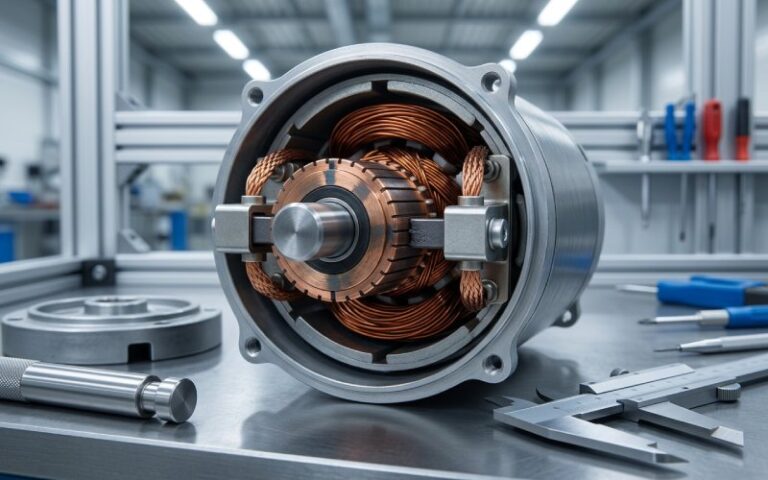
- In a brushed DC or universal motor, the commutator is a rotary switch fixed to the rotor.
- Brushes press on segmented copper bars and feed DC into the armature.
- As the rotor turns, the commutator reverses current in each coil every half-turn, so the magnetic forces keep pushing in roughly the same rotational direction instead of pulling back.
That’s the physics. Now to the real motive: how this piece of metal affects your KPIs.
3. The real purpose of the commutator in a motor
3.1 Convert “raw DC” into useful torque
On paper, the purpose of the commutator in a DC motor is to turn a simple DC supply into a sequence of timed current pulses in the armature coils. It’s a mechanical form of commutation or rectification.
In practice, that means:
- Continuous torque instead of oscillation
- Usable starting torque without external electronics
- An acceptable level of torque ripple for your load
If the commutator does this job poorly (wrong segment count, poor geometry, misaligned brushes), you get:
- Chatter at low speed
- Hot spots in the winding
- Extra stress on gearboxes and couplings
Same supply, same frame size, different commutator → noticeably different behavior.
3.2 Provide a controlled current bridge between fixed and rotating parts
Another purpose: reliable current transfer under moving contact.
- The commutator provides the copper path.
- The brushes define the sliding interface.
- Together, they form the only deliberate “wear pair” in the electrical path.
When that current bridge is stable:
- Your motor survives overload peaks without unpredictable arcing.
- EMI stays within what your product approvals expect.
- You can predict brush life to a reasonable band, instead of “somewhere between 2 months and 2 years.”
When it’s not stable, you start seeing random failures that look mechanical, but are actually commutation problems.
3.3 Shape efficiency, noise, and thermal behavior
Mechanical commutation inherently wastes some energy in brush–bar friction and arcing.
The purpose of good commutator design is not to remove this loss (that would be a different motor topology), but to keep it controlled and predictable:
- Smooth film on the copper
- Arc energy kept low enough to avoid bar damage
- Temperature in a range your insulation class can tolerate
That is why serious suppliers talk about:
- Bar material and purity
- Insulation between segments
- Surface finish and run-out tolerances
Those details show up later as:
- Lower brush dust in your enclosure
- Cleaner signal lines near the motor
- Fewer “mystery” overheats in high-duty drives
3.4 Enable simple control architectures
One more purpose that rarely appears in textbooks:
The commutator acts as a built-in commutation controller, so your external electronics can stay simple. Brushless motors move this job into silicon; brushed motors keep it inside the copper stack.
For many OEMs this still matters:
- Simple on/off or PWM control from a low-cost board
- Less sensitive to firmware bugs
- Easier supply chain: motor + basic driver, no custom FOC hardware
You pay with maintenance and life limits on brushes. But in commodity tools, automotive auxiliaries, or small appliances, that trade still wins.
4. How commutator design choices show up in your plant
Most articles stop at definitions. B2B buyers need the next layer: what design choices change what you actually see.
4.1 Segment count and geometry
Higher segment count, finer pitch:
- Smoother torque at low speed
- Lower ripple current → cleaner EMC in sensitive systems
- More complex manufacturing and potentially higher cost
Too few segments:
- Strong torque pulsations
- Easier to manufacture, but more mechanical vibration and audible noise
Global engineering references point out that practical commutators usually have at least three segments to avoid dead spots and allow acceptable current transition.
4.2 Materials and contact system
From copper purity to exotic alloy contacts, material choices exist mostly to support the commutator’s purpose under real operating stress:
- Standard copper segments: baseline conductivity and cost for most industrial DC motors.
- Copper-alloy or silver-bearing materials: better conductivity, higher thermal margin, used in demanding traction, aerospace, or high-temperature applications.
- Brush materials and grades: matched to the commutator to balance film formation, wear, and commutation quality. Wrong grade is a very common cause of poor performance.
You’re not just “buying copper”; you’re buying a tuned interface.
4.3 Insulation and mechanical structure
Insulation between bars and the way they are locked to the hub define:
- Maximum safe operating voltage
- Resistance to contamination and moisture
- How the surface responds to thermal cycling and mechanical stress
Technical guides on commutators list different constructions (V-ring, molded, riveted) with different repair strategies; some can be tightened and resurfaced, others must be replaced outright.
If your duty cycle is harsh and your repair windows are short, this becomes a sourcing question, not a trivia point.
5. When the commutator talks back: failure fingerprints
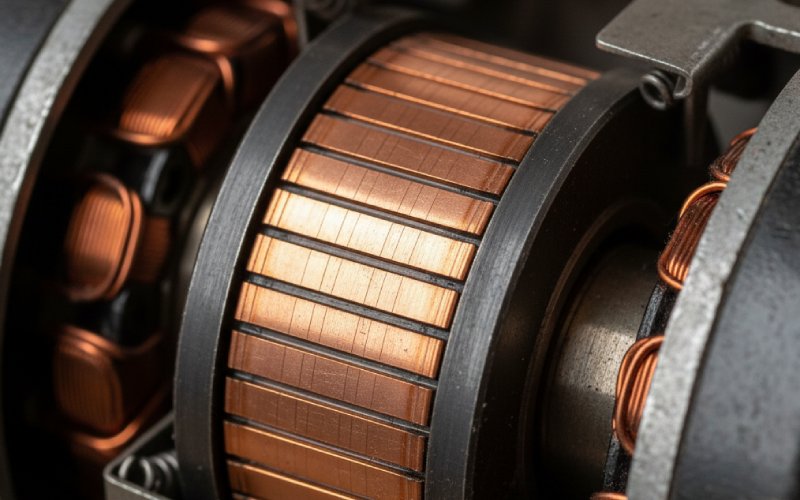
From a distance, a worn commutator just looks “brown and scratched.” Up close, the surface tells a story.
Specialist guides and industry experience describe recurring patterns:
- Uniform, smooth, chocolate-brown film
- Usually healthy. Correct brush grade, current density in range, temperature acceptable.
- Heavy grooving and ridges
- Often linked to hard brushes, contamination, or misaligned holders.
- Slot bar burning (etching on trailing edges in a repeating pattern)
- Signals that commutation is struggling: unsuitable brush material, poor electrical adjustment, or operation beyond designed load limits.
- Random pitting and freckling
- Brief overloads, poor connections, or vibration causing intermittent contact.
Why does this matter for the “purpose of commutator in motor”?
Because once the surface film degrades, the commutator stops performing its main tasks properly:
- Current reversal becomes more violent → more sparking
- Mechanical contact worsens → higher resistance and heating
- Maintenance intervals shrink and become less predictable
For a plant manager, that turns into:
- Unplanned line stoppages
- Increased brush and commutator replacement budgets
- Higher noise levels and EMC complaints in new equipment
6. Summary table: commutator purpose vs business outcome
Below is a compact way to see how one part connects to your metrics.
| Core purpose of the commutator in a motor | What it controls in practice | Key design / setup levers | Business impact if done well |
|---|---|---|---|
| Reverse armature current at the right time | Direction and smoothness of torque | Segment count, bar geometry, brush position | Stable motion, less vibration, fewer mechanical issues |
| Provide sliding electrical contact | Voltage drop, sparking level, EMI, brush life | Brush grade, spring pressure, surface finish | Predictable maintenance, fewer field failures |
| Manage thermal and mechanical stress | Surface temperature, copper and insulation aging | Bar material, insulation class, cooling and duty cycle | Longer motor life, fewer rewind or replacement events |
| Replace electronic commutation | Complexity of driver electronics, control strategy | Choice between brushed DC, universal, brushless alternatives | Simpler electronics, lower BOM in some applications |
| Maintain acceptable noise and feel | Audible noise, torque ripple, tactile feel in handheld products | Segment design, alignment, brush design, supply filtering | Better user perception, easier product certification |
You can read each row as: “If I let the commutator do this job well, I don’t need to fix the problem elsewhere.”
7. Brushed vs brushless: is the commutator still worth it?
Modern designs often compare brushed DC motors with brushless options where mechanical commutation disappears and electronics take over.
Very roughly:
- Brushed DC with commutator
- Simple drive circuits
- Lower upfront cost
- Limited life by brushes + commutator
- More maintenance, dust, and EMI
- Brushless DC (electronic commutation)
- Higher efficiency
- Much longer life; usually limited by bearings
- More complex and costly control electronics
- Often better for sealed, maintenance-free products
So when is a physical commutator still a rational choice?
- When you need short duty cycles and replacement is simple (power tools, automotive auxiliaries, low-cost pumps).
- When your electronics budget is tight, but occasional brush service is acceptable.
- When your market expects standard industrial DC motors that maintenance staff already know.
In those cases, the purpose of the commutator in the motor is not just technical; it’s to keep the overall system understandable and serviceable by the people you already have.
8. Practical checklist for B2B buyers and engineers
When you evaluate a motor or a standalone commutator–brush system, try asking suppliers questions like these:
- What brush grade is this motor designed around?
- Ask for recommendations under your actual duty cycle, not just nominal data.
- What commutator material and construction are used?
- Segmented copper with which insulation, which assembly method, and what surface finish specs?
- What are the limits for current density and surface speed?
- So you know how far you can push overload or speed before commutation quality collapses.
- What typical failure modes do they see in this series?
- A mature supplier should be able to describe specific surface patterns, causes, and mitigation steps.
- What maintenance interval assumptions are baked into their lifetime claim?
- Many brochures quote impressive hour numbers that assume clean, cool, intermittent duty.
- How does this motor compare to their own brushless offering for your application?
- You may discover that long term, removing the commutator is cheaper, even if today it isn’t.
This shifts the discussion away from just voltage/torque/price and toward the actual role of the commutator in your operating context.
9. FAQ: Purpose of commutator in motor – short answers to common queries
Q1. What is the main purpose of a commutator in a DC motor?
To periodically reverse the current in the armature windings so that the torque on the rotor stays in roughly the same direction, producing continuous rotation from a DC supply.
Q2. Does the commutator also exist in AC motors?
Not in most modern AC induction or synchronous motors. It is used mainly in DC motors, DC generators, and universal motors, where current direction in the rotor needs mechanical switching.
Q3. Can a motor run without a commutator?
Yes, but only if it uses a different commutation method:
AC induction or synchronous motors use alternating supply and rotor designs that don’t need a commutator.
Brushless DC motors replace the mechanical commutator with electronic switching in a controller.
Remove the commutator from a brushed DC motor without redesigning it, and it will not operate correctly.
Q4. Is the purpose of the commutator just to “convert AC to DC”?
In a generator, the commutator acts as a mechanical rectifier that turns internally generated AC into DC at the terminals.
In a motor, the more accurate statement is that it converts applied DC into alternating current inside the rotor coils at the right positions, keeping torque in one direction. Both descriptions refer to the same switching function, seen from different sides.
Q5. How does the commutator affect motor efficiency?
The commutator:
Adds friction and contact resistance, which lower efficiency.
Can introduce extra losses if surface film, brush grade, or contact pressure are wrong.
Good design keeps these losses small and stable; poor design or poor maintenance makes them grow over time.
Q6. What happens if the commutator is worn or damaged?
Typical effects:
Increased sparking at the brushes
Uneven torque and vibration
Rising temperature in the commutator zone
Shortened brush life
Guides on commutator maintenance describe issues like loose bars, slot bar burning, pitting, and grooving, all of which degrade the commutator’s ability to switch current cleanly.
Q7. Why are many new designs moving away from commutators?
Because mechanical commutators:
Need periodic brush replacement and surface maintenance
Produce dust and electromagnetic noise
Limit achievable speed and lifetime in some applications
Electronic commutation in brushless motors removes these constraints, at the cost of more complex control electronics.
Q8. For a new product, how should I decide if I still want a commutator?
Rough rule:
Choose brushed DC with commutator if you value low initial cost, simple control, and can accept serviceable parts.
Choose brushless or AC options if you value long life with minimal maintenance, better efficiency, and you’re willing to invest in more capable electronics.
Then refine the decision with your real duty cycle, environment, and service model.