Can You Polish or Burnish a Commutator for Better Conductivity?
Short answer: yes. But do it wrong and you’ll make everything worse. We’ve seen motors come back from the field with commutators polished to a mirror finish—gleaming copper, gorgeous to look at—and they lasted about seventy hours before the brushes chewed themselves apart.
The thing people get wrong: conductivity between brush and commutator isn’t really about how clean or shiny the copper is. It’s about the film.
Table of Contents
Key Takeaways
- Polishing a commutator can improve conductivity, but only when the existing surface film is damaged, glazed, or pitted. A healthy dark film should not be removed.
- Target surface roughness after polishing is Ra 0.4–0.8 μm. Going smoother (below Ra 0.1 μm) increases brush friction, causes chatter, and accelerates wear.
- Polishing removes material; burnishing compresses it. They are sequential steps, not interchangeable.
- If your commutators need frequent field polishing, the root cause is likely upstream—in segment geometry tolerance, copper alloy selection, or factory surface finishing. That’s a procurement problem, not a maintenance problem.
What Is Commutator Film (Patina) and Why Does It Matter for Conductivity?
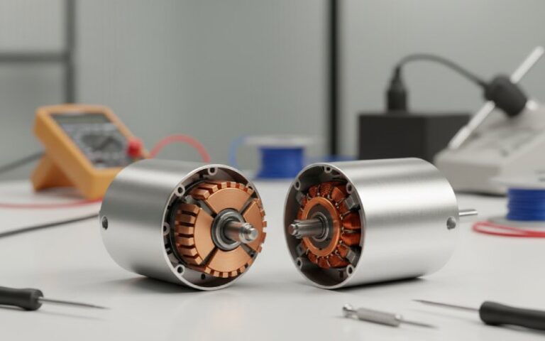
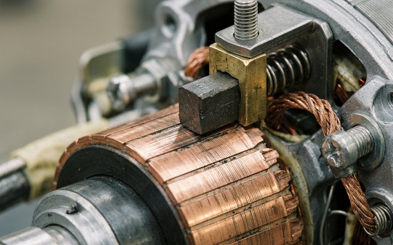
A healthy commutator doesn’t look clean. It looks like it has a tan. Sometimes chocolate-brown, sometimes darker. That layer—a mix of cuprous oxide (Cu₂O), trace graphite deposits, and absorbed moisture—is what actually makes the entire brush-commutator system work. Commutator film is the controlled-resistance interface that enables stable current transfer. It acts as a lubricant. It manages current transfer through fritting (voltage-driven micro-breakdown of the oxide layer) and quantum tunneling at the thinnest points. The oxide film is typically 10–100 nm thick on a well-functioning unit.
Strip that film by aggressive polishing? Now you’ve got raw copper against carbon brush. The friction coefficient spikes. The brush chatters. Arcing starts. You’re burning through brush stock at 3x the normal rate and you’re generating the exact same oxide film again anyway—except now it’s forming unevenly, with localized hot spots, and the whole runaway starts.
We’ve measured this directly in our test cells: a commutator that has been over-polished to below Ra 0.1 μm needs 40–60 hours of run-in time before brush wear stabilizes. One that’s finished correctly to Ra 0.4–0.8 μm stabilizes in under 10 hours.
Polishing vs. Burnishing a Commutator: Key Differences
This confusion costs people money. They’re not the same job.
| Polishing | Burnishing | |
|---|---|---|
| What it does | Removes material from the commutator surface | Displaces and compresses surface material without removal |
| Typical tools | Silicon carbide cloth (150–200 grit), commutator dressing stone, fine abrasive paper | Seasoned hardwood block shaped to commutator radius, or dedicated burnishing tool |
| When to use | After turning/grinding, to remove carbon buildup, to clean glazed or pitted surfaces | After polishing, to close micro-scratches and prepare surface for film formation |
| Risk if overdone | Removes too much copper, destroys existing healthy film, leaves surface too smooth | Minimal risk—worst case is wasted time |
| Target surface roughness | Ra 0.4–0.8 μm with peak-to-valley height of 6–10 μm | Maintains the roughness range set by polishing but closes micro-fractures |
| Conductivity effect | Temporarily increases resistance (film removed), then improves as new film forms | Negligible direct effect on conductivity; improves long-term film adhesion |
| Segment height tolerance | Must maintain ≤ 0.0015 mm bar-to-bar difference | No change to geometry |
Polishing is corrective. You do it when the surface is damaged—pitting, bar marking, carbon tracking, or burn spots. You’re machining the commutator.
Burnishing is finishing. You do it after polishing to close the micro-scratches that sandpaper leaves behind. Those invisible grooves are where uneven oxidation starts, and where arcing likes to initiate.
The ideal sequence: turn → polish → undercut mica → bevel segment edges → final polish with 150–200 grit SiC → burnish.
Commutator Reconditioning Methods: Stoning, Polishing, and Turning
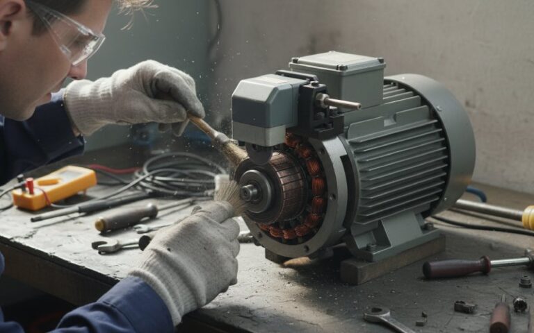
Dressing Stone (On a Running Motor)
The commutator runs at operating speed. You press a non-conductive abrasive stone—silicon carbide or aluminum oxide, bonded in a friable matrix—against the surface and traverse axially. The stone self-dresses as it works; dull particles break free, exposing fresh abrasive. Coarser stones (36 grit) eat flats and ridges. Fine stones (220 grit) do the final surface.
Do this at full speed. Centrifugal force holds the commutator bars in their true running position. Stoning at reduced speed gives you a surface that goes eccentric the moment the motor hits rated RPM.
One detail that gets skipped: vacuum the dust immediately. The residue from a dressing stone is conductive enough to cause inter-bar shorts if it packs into the mica slots. We run a negative-pressure extraction nozzle about 15 mm behind the stone at all times.
Why You Should Never Use Emery Paper on a Commutator
Only silicon carbide (SiC) cloth. Not emery. Emery contains metallic particles—iron oxide, corundum with ferrous inclusions—that embed in the copper and become conductive bridges across the mica undercuts. We’ve traced flashover failures directly to emery paper residue.
Wrap the cloth around a radiused hardwood block. The strip should span at least 150° of the commutator circumference. Press with the block, not your fingers. Finger pressure rounds off the segment tops, creating an uneven surface that the brush can’t track.
Diamond Turning (Factory-Level Reconditioning)
The diamond tip (75° included angle, R 1.58 mm top radius) takes cuts no deeper than 0.013 mm per pass. Feed rate stays under 0.13 mm/rev to avoid spiral grooving. This produces a near-burnished finish—which is actually too smooth for brush operation. You must break the surface afterward with 150–200 grit SiC cloth. Diamond-turned mica tends to sit slightly proud (about 0.005 mm), so the follow-up abrasive also relieves that.
PCD Finish Turning for New Commutator Production
For new commutator production, we use polycrystalline diamond tools (front angle γ = 12°, clearance angle α = 14°, nose radius R 0.1 mm). The challenge with copper: it’s soft, sticky, and generates heat fast. The PCD tool itself carbonizes above 700°C, so we run high-negative-pressure chip extraction and cool with high-speed airflow—no cutting fluid, which would contaminate the mica.
Runout target: ≤ 0.006 mm. Roundness: ≤ 0.003 mm. Bar-to-bar height: ≤ 0.0015 mm. Surface roughness: Ra 0.1–0.8 μm.
When Field Maintenance Points to a Procurement Problem
Here’s something worth sitting with. If your maintenance crew is polishing commutators every few hundred hours—if the film never stabilizes, if brushes keep wearing at 2–3x the expected rate—the problem probably isn’t the person holding the dressing stone. It’s the commutator itself.
The three most common upstream causes we see:
- Bar-to-bar height variation exceeding 0.002 mm at the factory. The brush bounces across the step like a car on a potholed road. Arcing follows. Film never forms evenly.
- Surface roughness out of spec from the factory. Either too smooth (mirror finish from lazy QC) or too rough (tool chatter marks from worn tooling). Both cause accelerated brush wear.
- Wrong copper alloy for the operating environment. Pure electrolytic copper is fine for moderate loads. High-current or high-temperature applications need silver-copper or cadmium-copper alloys that maintain hardness at elevated temperatures.
If you’re reading this because your machines keep eating commutators, the fix isn’t a better polishing technique—it’s a better commutator. That means tighter factory tolerances on segment geometry, proper PCD finishing, and copper alloy selection matched to your brush grade and duty cycle. This is what we engineer for every day.
When Polishing Improves Conductivity—And When It Destroys It
The relationship isn’t linear. Here’s what actually happens at the electrical contact:
- Dirty/glazed commutator → thick, uneven oxide and carbon film → high contact resistance → arcing → more uneven film → motor failure loop.
- Properly polished commutator → old film removed → clean copper with controlled roughness → new healthy film forms within hours → low contact resistance → stable operation.
- Over-polished commutator → mirror finish below Ra 0.1 μm → brush friction coefficient rises → brush chatters and bounces → intermittent contact → arcing → accelerated wear of both brush and commutator.
The sweet spot is scenario 2. But the catch: you need the right roughness range (6–10 μm peak-to-valley) with a high density of fine lathe marks. More marks per unit length = lower effective friction coefficient = faster, more uniform film formation.
A commutator that’s performing well—stable film, no excessive brush wear, no arcing—should not be polished just because it looks dark or patchy. Dark doesn’t mean dirty. The film color ranges from straw to near-black depending on humidity, load, and brush grade. If the machine runs fine, leave it alone. More commutator problems are created by unnecessary reconditioning than are solved by it.
Mica Undercut Inspection After Commutator Polishing
Polishing or turning a commutator reduces the copper height. If your mica undercuts were marginal before, they’re shallower now—possibly flush. Flush mica destroys brushes.
Check undercut depth before and after any surface work. The recess depth should not exceed the mica width. Walls of the segments must be completely clear of mica—a thin sliver left on the wall causes more trouble than flush mica does.
After undercutting, bevel the segment edges approximately 0.5 mm at 45°. A V-shaped scraper drawn along the recess bevels both adjacent segment edges simultaneously. Then clean, blow out every particle of copper and mica debris, and give the commutator its final pass with 150–200 grit SiC cloth.
Commutator Condition & Maintenance Decision Matrix
Use this when you’re standing in front of a motor trying to decide what to do:
| Commutator Condition | Action | Tool |
|---|---|---|
| Even brown/tan film, no arcing, brushes wearing normally | Do nothing | — |
| Light carbon tracking in mica slots | Clean slots with stiff brush, check undercut depth | Fiber scraper, paintbrush |
| Surface glazed, slippery, brush chattering | Light polish to break glaze | Fine dressing stone (220 grit) |
| Localized burn marks, pitting, or roughness | Polish to remove damage, then burnish | Dressing stone (coarse → fine), then hardwood block |
| Visible step between segments (> 0.025 mm bar-to-bar) | Machine reconditioning required | Turning (diamond or TC), then polish, undercut, burnish |
| Heavy grooving, severe eccentricity | Full reconditioning on lathe | Diamond turning → SiC finish → undercut → bevel → burnish |
| Copper drag across mica slots | Overheating problem—address root cause, then resurface | Investigate spring pressure, ventilation; then full reconditioning |
FAQ: Commutator Polishing and Burnishing
Q: Can I use regular sandpaper to polish a commutator?
Silicon carbide paper or cloth only. Standard emery contains metallic particles that lodge in mica undercuts and create conductive paths between segments. This leads to inter-bar shorting and flashover.
Q: How smooth should a commutator be after polishing?
Target Ra 0.4–0.8 μm with an axial peak-to-valley height of 6–10 μm. Too smooth (below Ra 0.1 μm) increases brush friction and prevents proper oxide film formation. Too rough accelerates brush wear.
Q: Should I polish a commutator while the motor is running?
Yes, for dressing stone work and light sanding—always at full operating speed so centrifugal force holds the bars in their true running position. Never attempt heavy reconditioning with the motor running. And always vacuum debris during the process.
Q: How often should commutators be polished?
Only when inspection shows a problem: burn marks, pitting, heavy carbon buildup, or measured bar-to-bar step exceeding 0.025 mm. There is no fixed schedule. Some machines run for years without needing surface reconditioning. More problems come from unnecessary polishing than from neglect.
Q: Will burnishing improve electrical conductivity directly?
Not measurably. Burnishing closes micro-scratches left by polishing, which promotes more uniform oxide film development—and that film is what governs long-term contact resistance. Think of burnishing as an investment in film quality, not a conductivity fix.
Q: Does humidity affect how fast the commutator film recovers after polishing?
Yes. At relative humidity around 50%, cuprous oxide forms reliably on the surface and acts as both a lubricant and a controlled-resistance layer. Below 10% RH, the oxide film may not form at all—brush wear rates increase dramatically, and seizure-type wear can take over.
Q: What’s the difference between a dressing stone and a grinding stone?
A dressing stone is designed for light, in-situ surface cleaning—it removes film and minor imperfections without significant copper removal. A grinding stone restores concentricity and removes substantial material. Using a grinding stone when you only need a dressing stone is how you end up with an undersized commutator and no mica undercut left.
Q: Can I polish a silver-copper alloy commutator the same way as an oxygen-free copper one?
Same general process, but silver-copper is more prone to heat buildup due to higher plastic deformation during cutting. Keep speeds moderate, use sharper tools, and be more aggressive about chip extraction. The surface roughness targets remain the same.
Frequent commutator reconditioning is a symptom, not a solution. If your motors keep developing film instability, brush chatter, or bar marking, talk to our engineering team about commutators built to tighter tolerances—matched to your brush grade, duty cycle, and operating environment.