Molded commutators vs. built-up commutators: key differences
Table of Contents
1. Molded vs. built-up commutators at a glance
Engineers often talk about “molded” vs. “built-up” as if they were just materials choices. They’re not; they are completely different ways to hold the segment pack together.
Quick comparison table
| Aspect | Molded commutator (molded shell / semi-plastic) | Built-up commutator (V-ring / mechanical) |
|---|---|---|
| Segment retention | Copper segments and mica encapsulated in thermoset/thermoplastic shell; segments held by molding compound and dovetails | Segments and mica stacked and clamped mechanically by steel or non-magnetic V-rings / clamping rings around a hub |
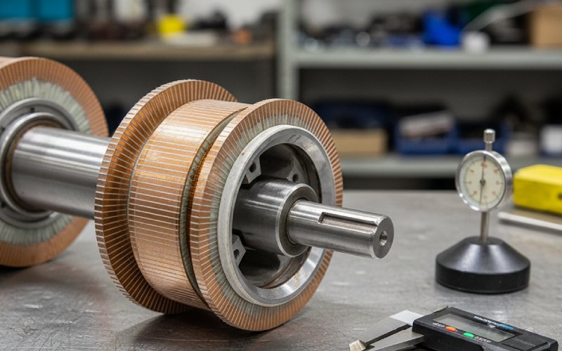
| Typical core | Phenolic, Bakelite, cast iron or other molded core, often with pressed-in bushing | Machined steel or iron core with separate segment pack and riser |
| Repairability | Generally non-repairable; not intended for refilling or segment replacement; whole rotor is replaced when worn or burned | Refillable / repairable; segment pack can often be turned, undercut, re-banded or even fully refilled on the existing core |
| Undercutting | Service manuals often warn: do not undercut molded types, as this can break the molded insulation and scrap the unit | Undercutting is standard practice during overhaul of many built-up units |
| Typical size range | Dominant in small and medium diameters (power tools, automotive starters, small industrial motors) | Common from small to very large diameters; traction, crane, mill, and other industrial DC drives |
| Speed / temperature tendency | Often chosen for heat-resistant and higher-temperature miniature motors; common in high-speed small motors | Traditionally favored for lower-speed machines, though modern designs cover a wide operating range |
| Field service | Treated as a throw-away component; rebuild shops sometimes convert them to V-ring style to make future repairs economical | Designed with service in mind: turning, undercutting, refilling, and re-banding are routine |
| Upfront tooling | Requires molding tooling; attractive in very high volumes and stable designs | More flexible for short runs, custom segment counts, design changes |
| Lifetime economics | Lower unit price but scrapped on failure | Higher first cost but lower lifecycle cost when field repairs are used seriously |
That’s the bird’s-eye view. Now the bits that usually swing decisions.
2. What is actually different in the construction?
You already know the textbook cross-sections. Let’s focus on what that means in practice when you’re designing, sourcing, or diagnosing.
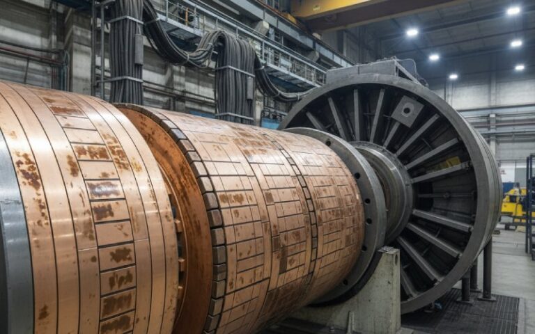
2.1 Segment pack and shell
Molded commutator
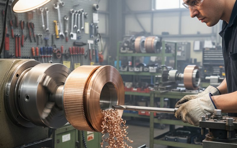
- Copper bars and mica are loaded into a mold or fixture.
- Molding compound (phenolic etc.) flows around the assembly and bonds bars, insulation, and hub as one shell.
- After curing, the commutator surface is turned. The shell does a lot of structural work.
Once that molded shell is cracked, carbon-tracked, or distorted, you’re finished. No practical way to “just replace a few bars.”
Built-up commutator
- Each segment is individually formed and slotted with a mica separator.
- The pack is assembled on a core or sleeve, then clamped by V-rings or bands.
- The mechanical clamping does the structural work; the insulation simply keeps bars apart.
Result: failure modes are different. Molded units fail like molded parts. Built-up units fail like mechanical assemblies.
2.2 Insulation and materials
Modern semi-plastic commutators (a common molded style) mix:
- plastic shell,
- copper segments or bars,
- mica or similar insulation sheets,
- metal bushing in the bore.
Built-up versions lean more on:
- copper + mica segment packs,
- glass banding or V-rings,
- steel core.
You see it in thermal behavior: molded materials limit how fast heat leaves the bar root, while a steel core conducts it away but might drive different expansion patterns. That comes back later when we talk about cyclic loading and bar movement.
3. Performance trade-offs that show up in testing
You don’t specify “molded” or “built-up” just from a gut feel. There are patterns.
3.1 Speed and operating temperature
A well-known miniature motor patent states it plainly: built-up types are usually used in low-revolution motors; molded types in heat-resistant motors.
Rough rules that often match what labs see:
- High-speed, small diameter, elevated ambient Molded commutators are common because the compact shell lets you keep the rotor small and manage thermal expansion in a predictable way.
- Large diameter, modest speed, serious torque Built-up mechanical commutators dominate. V-ring or glass-band construction handles the centrifugal loads of large segments better and is easy to service between overhauls.
It’s not that one is magically “faster.” It’s that their constraints line up with particular motor architectures.
3.2 Brush behavior and surface stability
Engineers typically worry about three things:
- Runout (TIR over time)
- Built-up units can be skimmed multiple times. Each skim shrinks diameter but restores a smooth track.
- Molded units can also be skimmed, but repeated machining eats into the molded shell. There’s no refill step later.
- Bar movement / slot opening
- Phenolic or Bakelite cores can relax under heat cycling, causing bar movement and uneven slots; rebuilders note this as a common motive to convert molded designs to V-ring types.
- In built-up designs, loss of V-ring pressure or band deterioration is the usual villain instead.
- Brush wear
- Once a molded shell distorts or cracks at the surface, brush wear tends to accelerate quickly, because you can’t re-pack the bars and reset clamping.
- With V-ring types you can skim, undercut, and re-band, resetting the sliding interface periodically.
So for a fleet owner who genuinely rebuilds motors, built-up construction behaves more predictably over multiple overhaul cycles.
4. Maintenance reality: what the manuals actually say
Service documents for many automotive starters and industrial motors include an all-caps warning that looks very familiar:
Some starters have a molded-type commutator. DO NOT undercut insulation; this may cause serious damage.
That shows up in multiple OEM service publications.
At the same time, ANSI-aligned repair guidance for DC machines states:
- If a commutator is molded or riveted, it is not considered repairable and should be replaced.
- V-ring mechanical commutators can be repaired.
Rewind and repair shops have adapted to that:
- A failed molded commutator is often re-engineered as a V-ring unit, letting them reuse a steel core and refill the pack in future.
- Built-up commutators are already refillable. Segment packs, bands, and risers can be replaced while keeping the hub.
So your maintenance strategy feeds back into the original choice. If your equipment is deliberately “non-rebuildable,” molded may be acceptable. If you live in a repair-heavy world, that choice becomes expensive quickly.
5. Cost structure: where each type actually wins
Let’s talk money, not only copper.
5.1 Upfront vs. lifetime
Molded commutators
- Need dedicated molding tools and fixtures.
- Shine in high-volume, long-running part numbers.
- Minimum economic lot sizes are usually larger.
- Unit cost is attractive when you ship millions and scrap the rotor when it’s done.
Built-up commutators
- Tooling is mostly in standard segment profiles, V-rings, and machining setups.
- Make sense for medium volume, high value motors, and for applications where rebuild shops are part of the story.
- Unit price is higher, but lifecycle cost per shaft-hour can be lower once you factor in refills and recuts.
If you are in purchasing, it’s easy to chase the lowest line item and forget that field rebuilders may quietly convert molded designs to V-ring anyway because they can’t economically service the original style. You then pay twice: once for the OEM part, again for the retrofit.
5.2 Risk of obsolescence
Design stability matters:
- Molded tooling changes are slow and not cheap.
- Built-up designs accept segment count changes, riser tweaks, and minor dimensional shifts with less tooling churn.
If you expect the motor platform to evolve — different windings, higher current density, slight diameter tweaks — building in a rigid molded shell early can lock you in.
6. When should you specify molded vs. built-up?
You will have your own internal rules, but a simple decision sketch helps cross-check.
6.1 Scenarios where molded commutators usually make sense
- Consumer power tools and appliances where:
- motor is not rebuilt in the field,
- unit price is very sensitive,
- lifetime is defined more by mechanical wear of the tool than by the commutator.
- Small automotive modules (window lifts, seat adjusters, some pumps) where:
- failures lead to unit replacement, not overhaul,
- packaging space for a V-ring structure is tight.
- High-volume miniature motors with demanding operating temperatures, where patents and production history already support molded designs.
6.2 Scenarios where built-up commutators tend to win
- Traction and crane DC motors, mill drives, rolling-stock auxiliaries:
- large diameters,
- high currents,
- formal overhaul cycles and stocked spares.
- Industrial DC motors where:
- workshop has turning and undercutting capability,
- the commutator cost is small compared with downtime.
- Aftermarket conversions of molded OEM designs:
- fleets decide they want refillable, rebuildable commutators instead of throwing away molded ones every time.
6.3 Trade-off checklist
When you are stuck between the two, this short checklist usually breaks the tie:
- Expected number of overhauls over machine life.
- Availability and skill level of local repair shops.
- Acceptable scrap rate (how many rotors you’re prepared to throw away).
- How frozen the motor design really is — honest answer, not the optimistic one.
- Impact of commutator failure: minor downtime vs. safety-critical.
7. What purchasing should send to the commutator supplier
Many sourcing problems start with incomplete drawings. Whether you go molded or built-up, send clean data.
At minimum:
- 2D drawing with:
- outer diameter, inner diameter, length of commutator,
- segment count and bar width at the surface,
- pitch circle, skew (if any),
- riser style and dimensions,
- ventilation features (webbed bore, cooling holes, solid bore, etc.).
- Target:
- maximum speed (rpm) and corresponding surface speed,
- continuous and peak current per path,
- expected temperature range at the commutator.
- Notes on:
- brush grade,
- environment (dust, oil, humidity),
- planned maintenance intervals.
Then one more line: “Molded” or “built-up” is not enough as a spec. Vendors need hard numbers to judge whether your preferred type is sensible or risky.
8. Engineering details that often get missed
A few small points that repeatedly show up in failure analyses:
- Thermal expansion mismatch The CTE of molded compound versus copper can drive stress at the bar roots. On built-up designs, clamp pressure and hoop stress in the rings become the tuning knobs instead.
- Balance across multiple re-cuts With built-up commutators, each skim reduces diameter and alters inertia. Make sure your balance allowances and minimum diameter spec are realistic.
- Brush grade choice vs. commutator style Aggressive brush grades chosen for molded shells (which may run hotter) might be unnecessary or even harsh on a cooler running built-up unit, and the other way around.
- Undercut strategy
- Molded: usually untouched, or only very shallow cleaning, per OEM repair instructions.
- Built-up: clearance and mica step are tuned purposely for the brush grade and current density.
These details are small individually, but together they decide whether your “same spec” molded and built-up options behave even vaguely alike.
9. FAQ: molded vs. built-up commutators
Q1. Are molded commutators always cheaper?
Usually per unit, yes, when you are in high volume and the tooling is already amortized. But once you consider:
scrap of non-repairable rotors, and
conversions to V-ring style during aftermarket repairs,
the total cost over life can favor built-up designs in heavy-duty applications.
Q2. Can I directly replace a molded commutator with a built-up one?
Not as a plug-and-play part in most cases.
You need to re-check:
shaft design and keys / splines,
available axial space for V-rings and riser,
rotor balance and inertia,
brush track position and length.
Many repair firms offer engineered conversions where they redesign the commutator and possibly the armature stack together.
Q3. Why do some manuals forbid undercutting on molded commutators?
Because undercutting cuts into material that is part of the structural shell, not just a simple mica spacer. Removing that material can crack the shell, loosen bars, and cause commutator failure. That’s why some OEMs explicitly warn against it in their starter motor procedures.
Q4. When is a built-up commutator overkill?
Single-use or non-rebuildable products.
Low-cost consumer devices where the motor is cheaper to replace than to open.
Tiny motors where the mechanical complexity of a V-ring design makes manufacture awkward.
In those cases, the serviceability advantage never pays back.
Q5. For a new industrial DC motor design, which type should I default to?
If the motor is:
larger frame size,
intended for overhaul instead of throw-away,
installed where downtime is expensive,
then a built-up mechanical commutator is usually the safer default. It keeps your options open: you can adjust clearances, bars, and bands as test data comes in, and repair shops worldwide understand how to service it.
Q6. What should I ask suppliers about quality control?
For either style:
Bar-to-bar resistance and high-pot test regime.
Maximum permissible TIR at surface and riser.
Spin test / overspeed practices, especially for high-speed or traction duties.
For built-up specifically:
How clamp pressure is controlled and verified.
Minimum refinish diameter and how many skims the design expects.
For molded:
Molding compound type and temperature rating.
History of bar movement or shell cracking in similar references.