Brushed vs Brushless DC Motors: Mechanical Commutator or Electronic Commutation?
When a motor project goes wrong, the root cause is often not torque. Not voltage either.
It is the commutation choice.
Too many designs are judged at the motor category level: brushed motor or brushless motor, brushed DC or BLDC. That is useful, but only up to a point. In actual production, the real question is simpler and harder at the same time:
Where do you want current switching to happen?
Inside the motor, through a mechanical commutator and brushes.
Or inside the drive, through electronic commutation based on magnetic position feedback or control logic.
Everything downstream changes from that decision. Wear pattern. Startup behavior. Noise. Service interval. Controller cost. Failure mode. Even how easy it is to explain the design to the end customer.
In our factory work, this is usually where the good projects separate from the expensive ones.
Table of Contents
Why this choice still matters in industrial DC motor design
A lot of buying teams already know the textbook difference between a brushed motor and a brushless motor. That part is not the problem.
The problem is that many comparisons stop at broad claims:
- brushed motors are simpler
- brushless motors last longer
- BLDC is more efficient
- mechanical commutators wear out
All true in a loose way. Not enough to make a safe OEM decision.
A mechanical commutator is not just an old solution. In many industrial programs, it is still the more workable one, especially when the system needs:
- direct DC supply
- simple startup under load
- controlled controller cost
- predictable field service
- easy replacement logic
- moderate speed with realistic maintenance access
On the other side, electronic commutation is often the better answer when the real pressure is on:
- continuous duty
- higher speed
- low maintenance expectation
- cleaner EMI behavior
- tighter closed-loop control
- better heat handling over long run time
That is the useful comparison. Not ideology. Application fit.
Mechanical commutator vs electronic commutation: the practical difference
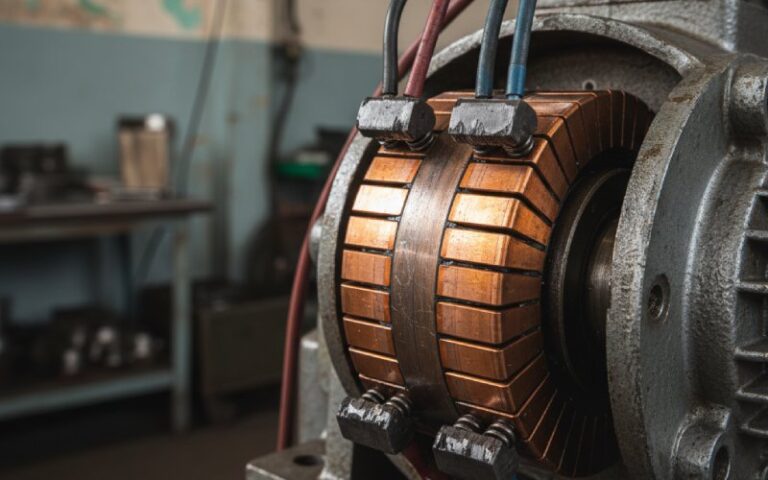
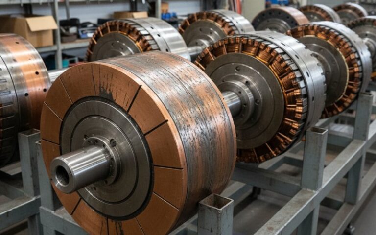
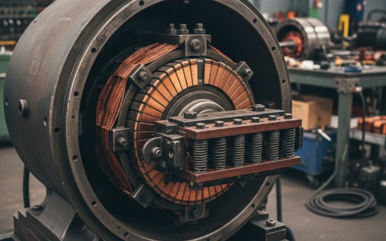
A mechanical commutator switches current physically through the brush and segment interface.
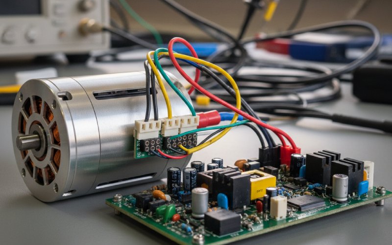
An electronic commutation system switches current in the controller, with rotor position taken from Hall sensors, other magnetic feedback, or sensorless estimation.
The first one solves commutation with parts that touch.
The second solves it with timing.
That sounds neat and clean. It is not.
Mechanical commutation brings contact wear, brush dust, surface tracking, arcing risk, and a very visible service life curve. You can inspect it. You can often predict the next failure before it arrives.
Electronic commutation removes the brush interface, yes, but it does not remove the commutation problem. It moves it into controller design, phase switching logic, sensor placement, startup algorithm, and noise behavior under real load. When it is done well, it runs beautifully. When it is done badly, the motor may still spin, but the system becomes noisy, unstable, hot, or strangely fragile.
We see both.
Quick comparison table
| Item | Mechanical Commutator (Brushed Motor) | Electronic / Magnetic Commutation (Brushless / BLDC) |
|---|---|---|
| Current switching | Inside the motor through brushes and commutator segments | Inside the controller through phase switching |
| Main wear point | Brush and commutator interface | Power electronics, sensors, switching quality |
| Startup at zero speed | Usually straightforward | Depends on control method; sensored systems handle this better |
| Maintenance style | Periodic service, visible wear, replaceable wear parts | Less routine motor service, more dependence on controller reliability |
| Thermal path | Heat concentrated in rotating armature can be harder to remove | Stator windings usually make heat removal easier |
| EMI behavior | Brush arcing can raise EMI and noise | No brush arcing, but switching noise still needs control |
| Speed range | Good for moderate speed; limited by brush and commutator behavior | Better fit for higher speed applications |
| Controller cost | Lower motor system complexity | Higher control complexity, more electronics |
| Field repairability | Often easier in traditional industrial setups | Usually lower at motor level, more drive-dependent |
| Best fit | Cost-sensitive, intermittent-duty, serviceable systems | High-duty, low-maintenance, higher-performance systems |
Where a mechanical commutator still wins
This part matters for buyers, because a mechanical commutator is often dismissed too early.
In real production environments, a brushed motor with a well-made mechanical commutator still makes very good sense when the system priorities are practical rather than fashionable.
1. When controller budget matters more than brochure efficiency
Some projects are cost-sensitive in the right place. Not cheap. Just disciplined.
If the machine needs stable DC operation without a more complex drive package, the mechanical commutator remains a strong choice. The motor architecture is simpler. The supporting electronics are lighter. Validation is often shorter. And when the duty cycle is intermittent rather than continuous, the life tradeoff can be very reasonable.
We still supply commutator programs for applications where this balance is exactly what the customer wants.
2. When startup has to be direct and predictable
A brushed motor does not need rotor position estimation to get moving.
That sounds obvious. It becomes important fast when the load is sticky, the power supply is basic, or the system must start reliably without much controller intelligence behind it.
In these cases, the mechanical commutator is not a compromise. It is the safer architecture.
3. When maintenance is acceptable, but downtime surprises are not
Brush wear is a disadvantage. It is also a visible one.
In many industrial plants, maintenance teams would rather deal with a wear component they understand than troubleshoot a control issue that appears only under certain speed and temperature combinations. That is a real preference in the field. Not every buyer says it early, but it shapes the final decision.
A commutator system can be inspected. Brush wear can be tracked. Segment surface condition tells a story. That service logic still has value.
4. When the environment is hard on electronics
Not every machine runs in a clean cabinet with friendly thermal margins.
Dust, vibration, unstable supply conditions, aggressive start-stop cycles, and limited controller space all push some projects back toward a more direct motor architecture. In those cases, the right question is not whether brushless is technically advanced. The right question is whether the total system becomes easier or harder to keep stable over time.
Sometimes the old-looking answer is the more industrial one.
Where electronic or magnetic commutation clearly pulls ahead
There are also many cases where a brushless motor or BLDC system is the right call from the beginning.
We do not pretend otherwise.
1. High duty cycle and continuous operation
If the motor runs for long periods, thermal handling starts to dominate the selection process. Electronic commutation usually has a better structural advantage here because the windings are fixed on the stator, so heat can leave the motor more directly.
That changes continuous-load capability. It also changes how much margin the design has when the real operating environment turns out worse than the lab test.
2. Low-maintenance products
If the business model depends on long service intervals, reduced field intervention, or sealed assemblies, brushless designs have a clear system advantage. No brush dust. No commutator track wear. Fewer wear items inside the motor itself.
Of course, the controller has to be done properly. But when it is, the maintenance story is better.
3. Better control flexibility
Speed regulation, current shaping, soft-start behavior, diagnostic functions, load response. These things are easier to build into electronically commutated systems. Not free. Easier.
If the motor has to work as part of a larger control architecture, not just spin, the value of electronic commutation rises quickly.
4. Higher speed programs
At higher speed, the brush and commutator interface becomes the wrong place to carry the switching burden. That is where brushless architectures usually become the cleaner solution from both life and stability perspectives.
The part buyers usually underestimate
The wrong decision is rarely caused by choosing brushed or brushless.
It is caused by choosing for the wrong reason.
Below are the most common mistakes we see when customers review mechanical commutator and electronic commutation options.
Mistake 1: Comparing only motor efficiency
This is one of the most common shortcuts.
A BLDC motor may look better on motor efficiency. Fine. But if the project adds a more complex controller, stricter EMC work, more validation time, and harder failure analysis in the field, the total system cost can move in the wrong direction.
A brushed motor may look less elegant. But if it shortens development, simplifies sourcing, and fits the duty cycle, it can still be the stronger industrial choice.
The motor does not live alone. The motor lives in a project.
Mistake 2: Assuming brushless means quiet and smooth by default
Not always.
If the electronic commutation timing is poor, if Hall placement is off, if the startup logic is rough, or if the application spends too much time in a weak operating zone, the system can produce torque ripple, switching noise, vibration, and audible electrical harshness.
No brushes, yes. No problems, no.
Mistake 3: Treating mechanical commutator life as a fixed number
Commutator life is not just a brush material issue. It is not just current either.
In our production reviews, the result is usually decided by a combination of:
- segment material choice
- brush grade matching
- surface finish consistency
- runout control
- current density
- spring force
- duty cycle reality
- PWM strategy in the complete system
That last one is often ignored too long.
A decent commutator can age badly in the wrong electrical environment. A well-matched one can run much more cleanly than expected.
Mistake 4: Using sensorless BLDC where the application does not support it
Sensorless electronic commutation can work very well in the correct speed window. But low-speed startup, unstable loading, repeated reversal, or heavy disturbance can expose its limits quickly.
If the application must start hard and start clean, the control method matters a lot. Buyers often compare motor types while ignoring that detail. Then later the motor gets blamed for a control decision.
What we look at first in commutator projects
When a customer sends us a new inquiry, we do not start with catalog language.
We usually start with five things:
- Starting condition
Is the motor starting unloaded, lightly loaded, or against real resistance? - Duty cycle
Intermittent, repeated short-cycle, or continuous run? - Operating speed
Moderate speed with service access is one world. High-speed sealed operation is another. - Controller reality
Is the customer actually prepared for a more advanced drive, or is the design still trying to stay electrically simple? - Service expectation
Is periodic maintenance acceptable? Or is the product expected to run long with minimal touch?
Most selection mistakes appear right there.
Not later in the datasheet. Right there.
How we improve mechanical commutator performance in production
When customers ask us to improve commutator life or reduce switching trouble in a brushed motor, we do not answer with a general statement like “optimize the design.” That does not help anyone.
We work the problem through production details:
Brush-track stability
If the contact path is unstable, the whole wear pattern becomes unstable with it. Surface consistency, concentricity, and segment transition quality matter more than many buyers expect.
Material pairing
The commutator material and brush grade have to be matched to the real current profile, not the ideal one. A mismatch may run acceptably in a short bench test and then degrade much faster in field duty.
Segment geometry
Segment count, insulation layout, edge condition, and mechanical precision all affect commutation quality. On higher-demand programs, small geometric errors show up as noise, local heating, or uneven wear.
Current density and overload reality
Some customers specify around nominal conditions and then operate around overload peaks. That gap matters. We review the current pattern early because commutator damage is often cumulative before it becomes visible.
Manufacturing repeatability
One good sample is not the target. Batch consistency is the target. For OEM supply, the real question is whether the commutator behavior stays controlled across volume production.
That is where factory experience matters more than nice wording.
Which option should you choose?
Here is the short answer we actually use.
Choose a mechanical commutator brushed motor when you need:
- simple DC architecture
- direct startup
- controlled electronics cost
- moderate speed
- serviceable wear parts
- practical field maintenance
- solid performance in intermittent-duty systems
Choose an electronically commutated brushless motor or BLDC motor when you need:
- long continuous duty
- lower routine maintenance
- better speed control
- higher operating speed
- improved thermal path
- tighter integration with advanced drive logic
- reduced dependence on brush-related service
If the application sits between the two, then the decision usually comes down to one thing:
Would you rather manage wear, or manage control complexity?
That is a blunt way to put it. Still useful.
Mechanical commutator or electronic commutation for OEM buyers
For OEM and industrial buyers, the selection should not stop at “which motor is better.”
A better question is:
Which commutation method makes the whole product easier to build, validate, ship, maintain, and explain?
That is the factory view.
If your team is building around cost discipline, straightforward service, and proven brushed motor architecture, a good mechanical commutator is still very much alive in modern DC motor design.
If your team is building around low-maintenance operation, tighter control, and higher duty demands, electronic commutation usually takes the lead.
Both can be correct.
The wrong part is choosing the right motor family for the wrong operating logic.
FAQ
What is the difference between a mechanical commutator and electronic commutation?
A mechanical commutator switches current physically inside a brushed motor through brushes and segmented copper surfaces. Electronic commutation switches current in the controller, usually in a brushless motor or BLDC motor, using position feedback or control logic.
Is a brushed motor always cheaper than a brushless motor?
Not always in total project cost, but often simpler at the system level. A brushed motor with a mechanical commutator can reduce controller complexity and shorten development in many industrial applications. A brushless motor may lower maintenance later, but the electronics burden is higher.
Is BLDC always better than a brushed motor?
No. BLDC is often better for continuous duty, higher speed, lower maintenance, and advanced control. A brushed motor can still be the better choice when startup simplicity, lower controller cost, and serviceable wear parts matter more.
When should I choose a mechanical commutator?
Choose a mechanical commutator when the application has moderate speed, realistic maintenance access, cost-sensitive control architecture, and a duty cycle that does not punish brush wear excessively.
Does electronic commutation remove all motor noise issues?
No. It removes brush contact noise and arcing, but poor switching strategy, weak startup control, or timing problems can still create vibration, audible noise, and torque ripple.
Can commutator life be improved without changing the whole motor design?
Often yes. In many cases, life improvement comes from better brush matching, segment precision, material selection, surface quality control, and more honest review of the real duty cycle.
Is sensorless BLDC suitable for all applications?
No. Sensorless electronic commutation is usually less comfortable at very low speed, under difficult startup load, or in applications with frequent abrupt changes. Those cases often need sensored control or a different motor strategy.
Need help choosing the right commutation method?
If you are comparing a mechanical commutator, a brushed motor, or a BLDC electronic commutation design for a new OEM project, send us the working data first:
- voltage
- current
- speed range
- startup load
- duty cycle
- brush material if already defined
- service-life target
- space limit
Our engineering team can review the application and suggest a commutator structure or motor-side adjustment that fits volume production, not just lab testing.