How interpoles (commutating poles) assist commutation in large motors
Large DC motors don’t “fail at commutation” in a neat way. They fail at the commutator. You see it in bar edge burning, brush face noise, tracking, odd film, a flashover story that starts with “it only did it under load.”
What matters on big frames is this: interpoles are the local, load-tracking correction that sits right where the commutator is asking for help. Not everywhere. Not forever. Just in the commutation zone, right now, at the current you’re actually running.
Table of Contents
Interpoles: what they’re really buying you on a commutator
Think of commutation trouble as two overlapping problems:
- The coil doesn’t want its current reversed that fast (reactance voltage is fighting the change).
- The neutral point isn’t where your brush rigging thinks it is (armature reaction shifts it, and it shifts with load).
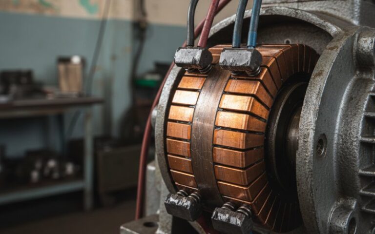
Interpoles are sized and connected so their effect rises with armature current—because they’re series with the armature. Few turns, heavy conductor, placed between main poles.
So when load rises and both the neutral-plane shift and the L·di/dt problem rise, the interpole field rises too, pushing back in the commutation zone over a wide range of loads.
This is why “just set the brushes” becomes a small-machine habit. On larger machines, changing brush position every time current changes is not the plan. Other means (interpoles / compensating windings) are used specifically because load current moves around.
Placement is the point (and also the limitation)
Interpoles are physically narrower than the main poles, usually similar length, and they sit between main poles.
They affect the few conductors being commutated. That’s their strength. Also their limitation. One set of lecture notes says it plainly: interpoles don’t fix flux distribution under the main pole faces; flux weakening issues can remain, especially on large machines.
So: if your commutator is sparking because the commutation zone is wrong, interpoles are the fix. If your commutator is unhappy because the whole pole face field is distorted under heavy load, you may be talking about compensating windings as well.
Not a contradiction. Just scope.
Polarity rules that still catch people
Polarity gets explained ten different ways. Here’s the version that survives a rewind shop and a midnight reversal:
- Motor: interpole polarity matches the main pole preceding it in the direction of rotation.
- Generator: interpole polarity matches the main pole following it in the direction of rotation.
Also: interpole flux always opposes the armature cross-flux.
And if you reverse the direction of rotation or reverse load current paths, don’t half-do it. One field note from industry is basically “reverse the interpoles too, or you’ll chase ghosts.”
Why “close enough” interpoles aren’t close enough on large motors
Two details from EASA are worth keeping on your wall:
- Final correction is often done on the test floor by adjusting interpole air gaps / shimming for best commutation.
- A change in interpole air gap as small as 1/64 in (0.4 mm) can cause bad commutation.
That second point is the quiet killer. You can have a commutator that looks like a brush-grade issue, but the real story is a shim stack that didn’t go back where it came from.
The “black band” is not theory; it’s a load-range sanity check
EASA describes the practical risk: if interpoles aren’t adjusted to keep brush neutral through the load range, the shifting neutral produces arcing outside the black band region, and that can trigger flashover.
Another description (same idea): vary the compole/interpole excitation and find the band where sparking disappears; outside it, you see trouble.
If you’ve never seen a machine that was “fine” at light load and then ate a commutator at production load, that’s basically the black-band story told with copper.
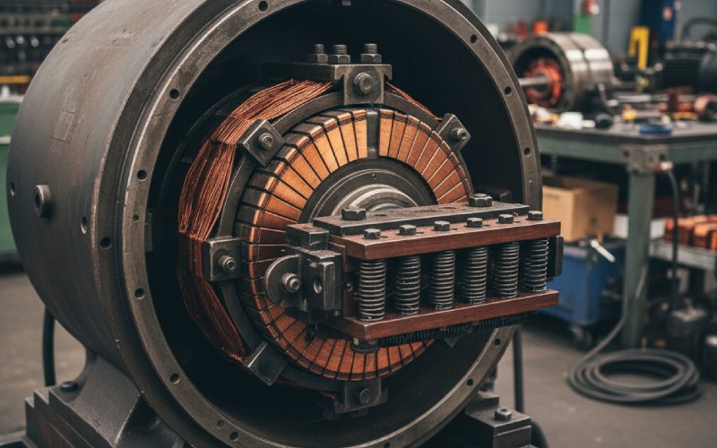
What the commutator shows when interpoles are off
One older maintenance paper says it in a way modern docs don’t: sparking becomes destructive when it works on the leaving edge of the commutator bar; when pits and streaks show up there, it’s time to correct the abnormal sparking conditions.
Same paper points out something else people forget: interpoles correct distortion in the commutation zone and can keep the machine running across the load range, but under heavy load they can saturate, and then sparking returns.
So you can’t read a commutator with one data point. You read it with:
- load level,
- direction,
- duty cycle,
- and whether you’re near saturation on the commutating poles.
Messy. Real.
A table you can actually use at the machine
| What you see at the commutator / brushes | Interpole-related suspicion | What to check next (fast) | Notes that save time |
|---|---|---|---|
| Sparking that grows with load; brush neutral seems to “walk” | Interpole strength not holding neutral across load range | Black-band style check; interpole air gap/shims; series circuit integrity | Poor adjustment across load range is tied to arcing and flashover risk. |
| Clean at light load, ugly at overload / peaks | Interpoles nearing saturation | Compare behavior at peak current; look for evidence of overcomp/undercomp; review any diverter/shunt arrangements | Saturation under heavy load is a known failure mode. |
| “It got worse after rewind” | Polarity wrong, or air gap/shims changed | Verify motor vs generator polarity rule; confirm A1/A2 reversal method if direction/current reversed | Reversing current needs reversal in both armature and interpole path, not just brush leads. |
| Bar edge burning / pitting biased to the leaving edge | Commutation not finishing inside the short-circuit window | Check interpole setting, brush seating, and mechanical brush-holder position | Leaving-edge damage is a classic “commutation ended too late” clue. |
| Random arcing that won’t tune out | Not only interpoles: brush mechanics, spring pressure, brush grade | Spring tension measurement; holder condition; brush grade confirmation | Too little spring tension raises resistance and heat; measure with a scale. |
| “We changed brush grade and it changed everything” | Interpoles were marginal; brush drop was carrying the last bit | Confirm brush grade suitability; don’t mix grades casually | Brush contact drop is part of commutation; designers expect it to help. |
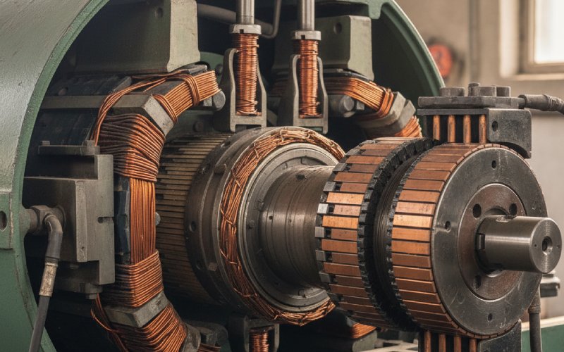
Interpoles don’t work alone (brushes are part of the commutation system)
Brushes aren’t just current carriers; they help current reversal in the short-circuited coil without blocking useful load current. That’s not marketing copy—Helwig’s maintenance note states it directly.
Also, the same note points out why you can’t design away everything with interpoles: armature reaction varies with load and speed, and the shorted coil inductance doesn’t disappear. Compromise is built in.
Practical takeaway: if you tune interpoles and ignore brush contact conditions, you’re only tuning half the commutator’s reality.
Plant Engineering’s old-but-still-true reminder: insufficient spring tension is worse than too much, and it’s easy to measure with a simple scale method.
Interpoles vs compensating windings (on big frames, you often need both)
Interpoles: cancel commutation-zone voltage problems and track load because they’re series connected. Compensating windings: address flux distortion under pole faces; they’re expensive (machining into pole faces), and machines with compensating windings still use interpoles to cancel L·di/dt effects.
If your commutator problem shows up as “everything shifts under load” plus “field under pole faces looks distorted,” you’re not choosing one. You’re sequencing the work.
A few “shop-floor” patterns that keep repeating
- Air-gap shims get mixed or swapped. Then you chase a brush grade for weeks. EASA’s tolerance note (1/64″) is why this matters.
- Direction reversal gets wired like it’s a small motor. Brush lead changes alone don’t guarantee the interpoles follow.
- Interpoles are “about right,” until the duty cycle changes. Peaks, plugging, rapid reversals. That’s where marginal settings show.
- People treat commutation as magnetic only. Then spring pressure and brush seating quietly undo the tuning.
Not perfectly logical, but it’s how it shows up.
FAQ
What exactly are interpoles cancelling?
Two things, usually discussed separately: the reactance voltage in the coil being commutated and the effect of armature cross-flux in the commutation zone. EASA describes the interpole flux requirement as cancelling both.
Why are interpoles series-connected to the armature?
So their effect scales with load current, keeping balance with the armature effects they’re correcting. EASA and multiple training notes state they’re connected in series for this reason.
Motor vs generator polarity — what’s the simplest rule?
Motor: interpole matches the preceding main pole. Generator: interpole matches the following main pole.
Can interpoles be “right” at one load and wrong at another?
Yes. That’s the whole point of black-band thinking: there’s a band where commutation is spark-free, outside it you see sparking, and it can shift with operating conditions and adjustment.
Do interpoles ever saturate in real life?
They can. One industry paper notes sparking may occur if interpoles become saturated under heavy load.
If we reverse rotation, do we have to do anything with interpoles?
You have to make sure the interpole polarity relationship still matches the motor/generator rule, and that reversal of current is handled in both the armature and interpole path (not only brush connections).
Are brush issues “separate” from interpole issues?
Not really. Brush contact behavior (including brush drop and seating) is part of the commutation system, and maintenance guidance explicitly treats it that way.