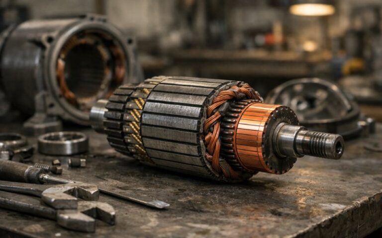
How to Make a Commutator: A Practical Manufacturing Guide for DC Motor OEMs
This article is about the actual build — what has to happen on the factory floor if you want a stable, low-noise commutator that survives speed, heat, and purchasing’s cost pressure.
Most public articles stop at “copper bars + mica + compression and bake”. Let’s go one level lower: choices, trade-offs, and process details that quietly decide whether your next DC motor program is smooth or a warranty line item.
Table of Contents
1. Quick View: Commutator Manufacturing Flow
For reference, here’s the short version of a typical hook or riser commutator build:
- Define application envelope and commutator spec.
- Select construction (molded, glass-banded, V-ring, refillable, etc.).
- Prepare copper and insulation:
- Draw / extrude copper bar
- Stamp trapezoidal segments
- Prepare mica / insulation pack
- Form segment geometry (hook legs, dovetails, notches).
- Stack segments + insulation and compress / mold into a pack.
- Run seasoning cycles (compression + thermal).
- Machine bore, OD, and slots; slit segments; undercut mica.
- Form hooks / risers, machine coil slots, plate if needed.
- Spin test, dynamic seasoning, and inspection.
Everything else is just you trying to hit tolerances and keep brush wear sane.
2. Start with the Application Envelope
If you skip this and just “copy last year’s commutator”, problems often show up in the endurance lab.
A minimal envelope for how to make a commutator that actually fits your job:
- Motor type DC traction, automotive starter, small appliance, universal motor, lab machine… each pushes different limits (current density, speed, vibration).
- Speed window Max mechanical RPM, overspeed requirement for spin test, duty cycle.
- Load profile Continuous, start-stop, stall risk, regenerative operation.
- Environment Humidity, contaminants, shock / vibration, salt spray, temperature peaks.
- Brush system Carbon grade, brush size, spring force. The commutator has to cooperate with that, not fight it.
You’re not writing a spec here; you’re defining the “why” that will drive segment count, copper grade, insulation system, and seasoning strategy.
3. Choose the Commutator Construction
Competitors often list construction types like a brochure. Let’s be more blunt.
Common options you’ll actually see in RFQs and drawings:
- Molded commutator
- Segments + insulation embedded in a molded thermoset hub (often phenolic).
- Good for small / medium motors, high volumes.
- Not repairable. When it’s done, it’s scrap.
- Glass-banded commutator
- Copper + mica pack, restrained by glass-fiber bands and resin.
- Good at high speeds and shock, popular in traction and heavy duty.
- V-ring / shrink-ring / steel-ring types
- Mechanical rings clamp the pack to a steel hub.
- Refillable designs allow segment replacement on large machines.
- Plane / shell-type commutators
- Often cold-extruded shells plus molding; used where axial space is tight.
While you decide, keep three quick questions in your notes:
- Will this construction allow static and dynamic seasoning to the level your spec wants?
- Is repairability relevant for your customer at all, or is this motor disposable?
- How does the design behave at overspeed when resin creeps and band tension changes?
If your answers are fuzzy, the design isn’t ready to build.
4. Copper and Insulation Preparation
Everyone writes “high-grade copper” in brochures. The question is: which copper, and how do you handle it?
4.1 Copper bar / hoop
Typical steps:
- Select copper or copper-alloy grade for the current density and environment.
- Draw or extrude bar or hoop to the pre-segment profile.
- Control grain size and hardness so you can form hooks later without cracks.
For many commutators you’ll see trapezoidal bar stock so that end-view segments naturally wedge around the circumference.
4.2 Segment insulation
Still, very often:
- Mica (segment mica, built to handle compression and temperature) between segments.
- Additional V-rings or molded insulation between the copper pack and the steel hub.
You know the drill: thickness, shear strength, and thermal class must match the application. Over-spec here and procurement will complain; under-spec and root-cause reports get busy.
5. Segment Forming and Punching
This is where a lot of patents live, but the practical sequence is surprisingly similar across plants.
5.1 Hook-type segment processing
Typical process for a hook-type commutator:
- Blanking & drawing
- Copper material is blanked and drawn into a bar.
- Progressive punching
- On the bar:
- Hook leg shape
- Dovetail groove
- Notch for the lower groove or relief
- All punched in staged dies to keep positional accuracy.
- On the bar:
- Segment cut-off
- Segments separated from the processed bar.
- Cleaning and deburr
- Degreasing, tumbling, or brushing to remove burrs before stacking.
You’ll tweak the die set for your exact geometry, but the rhythm is usually that.
5.2 Alternative shell / plane constructions
For plane or shell commutators, it’s common to:
- Form a continuous copper shell (cold extrusion, forming).
- Add slits / pawls around the circumference.
- Mold the insulating boss inside the shell.
- Cut slits fully through to create segments.
Useful where axial length is limited or you want a flat commutator disc.
6. Stacking, Molding, and Static Seasoning
Once you have segments and insulation, now you’re essentially building a copper-mica “log” and forcing it into behaving like a single stable part.
6.1 Stack-up
- Arrange copper segments with mica segments between them.
- Insert into a steel or tool-steel compression fixture or mold.
- Add V-rings or support members as required by the design.
6.2 Compression and molding
Two typical paths:
- Injection / compression molded commutator
- Put segments + mica + insert into the mold.
- Inject thermoset resin (e.g., phenolic).
- Cure under pressure.
- Glass-banded / ring construction
- Apply axial compression to consolidate copper + mica pack.
- Install glass banding, bands pre-impregnated with resin.
6.3 Static seasoning
Most serious suppliers now run multiple compression + bake cycles. The pattern is usually:
- Cold tightening of the fixture.
- Heat soak at not less than roughly 160 °C for several hours (exact recipe is proprietary).
- Hot tightening while the pack is still at temperature.
- Repeat cycles as needed for size, speed, and application.
The point is boring and important: you want creep, resin shrinkage, and internal movement to finish before the commutator ever sees a brush.
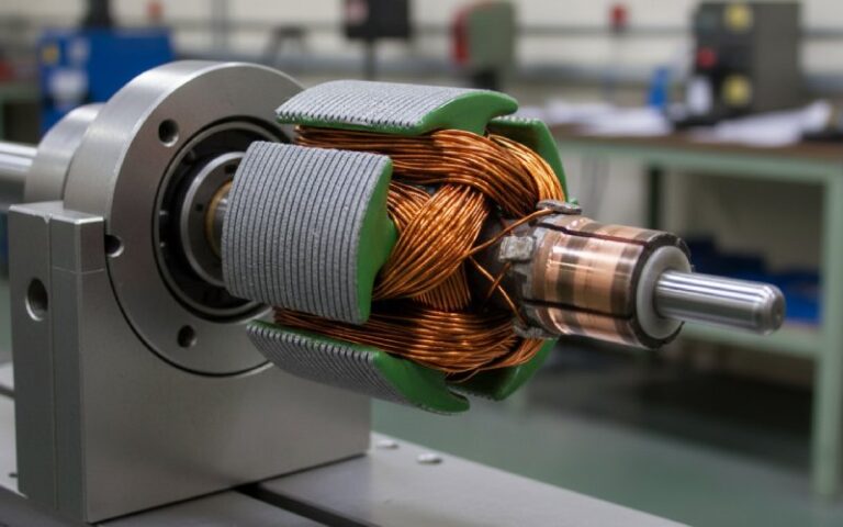
7. Machining: Turning, Slotting, Slitting, Undercutting
This is where you visually recognize it as a commutator.
7.1 Bore and OD machining
- Ream or bore the inner diameter to fit the shaft or hub.
- Turn the outer diameter to near-final size, with allowance for finishing.
At this stage you start tracking run-out and concentricity; you know the brush track can’t fix geometry errors later.
7.2 Slotting, slitting, and undercutting
Typical sequence:
- Segment slotting (where needed)
- Axial slots in the copper for coil leads or riser features.
- Slitting
- Cut axial slits between segments to separate them electrically.
- Mica undercutting
- Remove mica slightly below the copper surface to keep brushes running on copper, not insulation.
- Edge conditioning
- Chamfer segment edges to control brush wear and reduce chipping.
At this point the copper-mica pack is close to its final electrical role, even if it doesn’t look pretty yet.
8. Riser / Hook Forming and Conductor Connection
Now you prepare the actual termination points for the armature coils.
8.1 Riser and hook formation
Depending on commutator type:
- Hook type
- Pneumatically or mechanically bend the hook legs.
- Check for cracks or strain marks at the bend.
- Riser type
- Machine down excess copper to form radial flanges.
- Cut slots or pockets into each flange for coil ends.
- Composite riser designs
- Braze or weld riser blocks onto bars, where higher current or special geometry is required.
8.2 Conductor connection approach
Methods you’ll see in specifications and older methods:
- Brazing / resistance welding / TIG
- Favored when you want high-temperature stability and reliable joints.
- Soldered joints
- Historically common but known to soften under high temperature and current; many designs have moved away from relying on solder only.
Connection method drives inspection: you’ll adjust non-destructive tests (visual, X-ray, electrical) around it.
9. Finishing, Dynamic Seasoning, and Inspection
The part is almost a commutator. Now you make it behave like one in a real motor.
9.1 Surface finishing and plating
Common finishing steps:
- Final grinding / turning of the commutator track.
- Grooving or surface patterning, if your brush spec calls for it.
- Plating of segments (tin, nickel, silver, or gold, thin layer) where corrosion, low contact resistance, or special contact behavior is required.
9.2 Dynamic seasoning / overspeed test
To simulate real use and stabilize the pack:
- Spin seasoning
- Run at or above rated speed, sometimes at controlled temperature, to let internal stresses settle.
- Overspeed testing
- Validate mechanical integrity at a defined overspeed factor (e.g., 1.2–1.5× rated).
On traction, aerospace, or nuclear work this part of the process tends to be strict and non-negotiable.
9.3 Electrical and dimensional checks
Key checks, no theory needed:
- OD, ID, and face run-out
- Segment alignment and bar-to-bar concentricity
- Bar-to-bar resistance and insulation resistance
- High-potential (hipot) tests between segments and to hub
- Visual: cracks, porosity, plating defects, undercut quality
Once all this passes, the commutator is actually ready to see an armature.
10. Example Process Choices by Application (Table)
A quick comparison to organize thinking when you’re asking “how should we make this commutator” for different OEM programs:
| Application type | Typical commutator construction | Segment count (typical) | Insulation system | Seasoning approach | Notes for OEM teams |
|---|---|---|---|---|---|
| Small appliance / power tool DC or universal motor | Molded commutator on thermoset hub | 8–36 | Mica between segments + molded phenolic | 1–2 static seasoning cycles, basic spin check | Low unit cost, usually non-repairable. Design for automated assembly. |
| Automotive starter motor | Molded or glass-banded hook commutator | 20–40 | Segment mica + glass band or V-rings | Multiple seasoning cycles, defined overspeed margin | High current and shock; pay attention to riser geometry and brazed joints. |
| Traction / heavy industrial DC motor | Glass-banded or steel-ring refillable commutator | 60–200+ | Segment mica + rings, high-class insulation | Static seasoning with several compression / thermal cycles; dynamic seasoning at controlled temperature | Large diameter, long life, serviceable. Strong focus on refillability and inspection access. |
Use this as a sanity check: if your new design sits far outside these patterns, either you’ve innovated for a reason or something basic got missed.
11. Common Build Mistakes (and Quick Fix Ideas)
A few problems that show up again and again in commutator manufacturing audits:
- Under-seasoned copper–mica pack
- Symptom: bar movement, uneven brush track, out-of-round growth during service.
- Fix: add seasoning cycles or adjust time/temperature/tonnage; verify via sample spin tests.
- Over-aggressive undercutting
- Symptom: mica crumbling, brush chipping.
- Fix: tighten depth control, refine tool geometry, review cooling and chip evacuation.
- Poor hook or riser forming
- Symptom: micro-cracks at bends, high joint resistance later.
- Fix: re-tune bending tooling; keep bending radius, temperature, and copper hardness aligned.
- Contaminated surfaces before brazing / welding
- Symptom: random high-resistance joints under load.
- Fix: introduce strict cleaning step and handling rules before joining.
- Ignoring brush–commutator interaction in design
- Symptom: acceptable drawings, but in test you get noise, sparking, or rapid brush wear.
- Fix: treat brush grade, spring force, and commutator finish as a single system and iterate.
- Loose controls on OD and run-out
- Symptom: intermittent contact, localized heating.
- Fix: improve fixturing and in-process gaging during turning and grinding.
- Ad-hoc process changes not reflected in documentation
- Symptom: batch-to-batch variation with no obvious root cause.
- Fix: lock process windows (compression tonnage, bake time, material batch limits) and treat them like any other critical characteristic.
12. FAQ: Practical Questions About Making Commutators
Q1. Which copper grade is best for commutator segments?
There’s no single answer. High-purity copper alloys are typical for their conductivity and wear behavior, with variations based on current density and mechanical stress. Many manufacturers use copper alloys tuned for specific sectors like automotive or traction.
Q2. Do I always need multi-cycle compression seasoning?
If you’re building anything beyond very small low-stress motors, yes, it’s hard to justify skipping it now. The combination of repeated compressions and bakes stabilizes the copper–mica pack and reduces in-service movement, which is especially important in traction and other critical machines.
Q3. Can commutators be repaired, or are they always disposable?
Small molded commutators in tools and appliances are usually not repairable; the cost of rework is higher than replacement.
Large industrial and traction commutators are often designed as refillable, allowing replacement of copper segments and re-machining of the pack.
Your commutator construction choice at design time largely decides this.
Q4. What’s the practical difference between molded and glass-banded commutators?
Molded: resin hub, simpler integration, often better suited to automation, lower piece price in high volume.
Glass-banded / ring types: better mechanical retention at very high speeds and in high-energy environments; commits you to stronger seasoning and inspection routines.
Q5. How “finished” should the commutator be before armature assembly?
In most DC motor factories:
Bore, OD, and undercut are complete.
Hooks / risers are formed and inspected.
Dynamic seasoning and a basic spin test are done.
Some OEMs then run a final skim cut on the commutator after armature winding and impregnation to correct small distortions from curing and assembly.
Q6. Can additive manufacturing replace traditional commutator processes?
For now, not for mainstream production. The combination of high-purity copper, fine segment geometry, and proven insulation systems still favors drawn bar, stamping, molding, and machining. Additive methods might appear in fixtures, prototypes, or auxiliary parts, but not yet as a standard segment build path.