How Does a Commutator Work? A Practical View
Short version: a commutator is not just “a rotating switch”. It’s a tightly-timed current-reversal machine that lives on the edge of sparking, heat, and noise every second of its life.
Table of Contents
1. Quick reality check: what “working” actually means
You already know the textbook line:
A commutator reverses the current between the rotor and the external circuit in DC motors and generators.
Fine. But in a B2B context that’s not enough.
For you, a commutator “works” only if all of these stay under control:
- Current reverses in the right coil at the right electrical angle.
- Torque ripple and voltage ripple stay inside your spec.
- Brush wear and commutator wear land inside your maintenance window.
- EMI, noise, and heat don’t break the system.
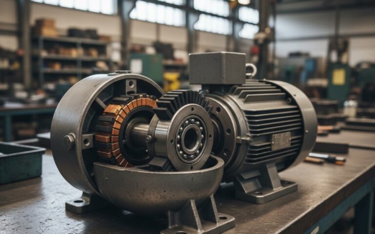
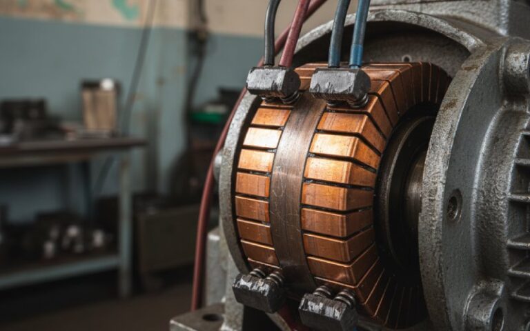
The copper cylinder with segmented bars, insulation, and brush track is just the hardware shell for that behaviour. One major motor glossary describes it as a multi-segment copper ring on insulated support, converting DC from the brush into alternating currents in the rotating armature with precise timing and polarity.
So: the “how” is really how the interface behaves, not just how it looks in a cross-section drawing.
2. The commutation window: a few milliseconds that decide everything
Most competitor articles stop at “brush touches segment, current reverses”. Let’s zoom in closer than that, but not drown in math.
2.1 Brush footprint and segment bridging
Real brushes aren’t razor thin. A typical carbon brush spans roughly 2–3 segments as it rides on the commutator surface. That means for a short interval it electrically shorts adjacent segments, tying two coils together while current transfers.
In that tiny angular window:
- One coil’s current must ramp from +I to −I.
- The neighboring coil must ramp from −I to +I.
- The brush short-circuits them while this happens.
So you have:
- Large di/dt in a small inductive loop
- Local EMF from self-induction, fighting the reversal
- Heat and potential sparking at the leading/trailing edges of the brush
If the inductive kick plus supply voltage is not well balanced, you see:
- Strong blue arcs at the edges of the brush
- Bar-to-bar burning patterns
- Audible “buzz” at certain loads and speeds
That’s still the commutator “working”, but doing damage while it works.
2.2 Commutating plane and brush position
Beginner diagrams put the brushes exactly at 90° electrical from the field. Real machines don’t stay that ideal.
- Armature reaction shifts the magnetic neutral plane.
- Self-induction means current lags even when your geometry is perfect.
So the effective commutation plane is moved forward or backward, and the brush holder has to follow that shift (or the field must be corrected).
Designers use:
- Interpoles / commutating poles to inject a compensating field in the commutation zone, killing the reactance voltage in the shorted coil.
- Compensating windings in the pole faces for motors with heavy armature reaction, stabilising the neutral zone over a wide load range.
If those are tuned correctly, brush position can stay fixed over load, speed, and direction changes without unacceptable sparking. If not, your “how it works” becomes “how fast it erodes”.
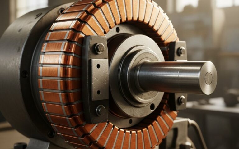
3. Inside the hardware: how design choices shape behaviour
Construction basics are common: copper segments, insulated from each other and from the shaft, clamped together as a cylinder, with spring-loaded brushes pressing on the surface.
But small differences here change everything downstream: losses, life, and commutation quality.
3.1 Key commutator design levers (summary table)
| Design lever | Typical options | What it really changes | Use-case hints |
|---|---|---|---|
| Segment count | Tens to hundreds of bars | Electrical angle per bar, torque / voltage ripple, commutation time per coil | More segments → smoother torque and lower ripple but tighter tolerances and higher cost. (维基百科) |
| Segment material | ETP Cu, Ag-Cu alloy, other copper alloys | Resistance, hardness, wear pattern, temperature rise | Harder alloys improve life at high speed but can be harsher on brushes. |
| Insulation | Mica, epoxy resin, engineered plastics | Max temperature, mechanical robustness, undercut quality | High-temp insulation matters in power tools and automotive; consumer motors live with cheaper molded variants. |
| Construction | Dovetail “refillable”, shrink-ring, molded | Serviceability, runout control, cost structure | Large industrial DC machines favour refillable; small appliances usually use molded, non-serviceable units. |
| Diameter & surface speed | Sized for target RPM and torque | Peripheral speed, centrifugal stress, frictional heating | Pushing surface speed too high without adjusting brush grade leads to rapid wear and dust. |
| Surface finish | Ground, polished, grooved patterns | Film stability, initial wear-in, noise | Too smooth can give unstable films; too rough accelerates brush wear. |
| Brush material | Pure carbon, metal-graphite, copper | Contact drop, current density capability, lubrication | High current density or low voltage? You likely end up with metal-graphite or copper-graphite grades. |
| Brush pressure | Light, medium, heavy (per supplier data) | Contact stability vs. mechanical loss and wear | There is an optimum window; above it you grind the commutator, below it you get intermittent contact. |
| Slot / pole / bar combo | Slot-per-pole, complex fractional schemes | Harmonics, torque ripple, commutation EMI | This is where motor and commutator design really merge; you can’t treat them separately at higher power levels. |
Most competitor blogs never leave the top row of that table. For a B2B buyer, the lower rows are exactly where specification risk hides.
4. Motor vs generator vs universal motor: same ring, slightly different job
Yes, a commutator in a DC motor and in a DC generator looks almost identical. But the system around it changes how it “works” in practice.
4.1 DC motor
- Supply delivers DC at the brushes.
- Commutator feeds controlled AC into the armature coils, flipping their polarity every half turn relative to the stator field.
- Result: torque stays roughly in one direction, even though each conductor sees alternating current in rotor coordinates.
Your concern: torque ripple, speed response, and brush life under your real duty cycle.
4.2 DC generator
- Mechanical torque rotates the armature.
- Coils generate AC (in armature coordinates) as they cut the field.
- Commutator collects that and outputs “rectified” DC at the brushes.
Same copper, different viewpoint: here the commutator is effectively a mechanical rectifier, and ripple at its output dominates downstream filtering and regulation design.
4.3 Universal and special machines
Universal motors, repulsion-induction motors, and similar designs still rely on commutators, but use them in slightly different ways: many use AC at the brushes and let induced currents in the rotor act through the commutator.
There are even newer DC designs with inverted mechanical commutators where the commutator is stationary and the brush carrier rotates, aiming to reduce stress and improve geometry at higher speeds.
From a sourcing standpoint, those details matter because they change:
- Required insulation class
- Segment connection method (hook type vs groove type)
- Allowable runout and balancing strategy
5. How a commutator quietly fails while still “working”
A lot of motors reach end of life not because the windings burn, but because the commutator-brush system slowly crosses a line from stable to unstable.
Some common signatures engineers see on teardown:
- Bar-to-bar burning patterns
- Dark, overheated bars around the neutral zone.
- Often shows poor commutation timing or wrong brush grade.
- Grooving and threading
- Spiral marks along the commutator surface, usually following brush grain.
- May come from abrasive particles, misaligned brush holders, or wrong brush hardness.
- High mica
- Insulation stands proud of the copper after wear, lifting brushes at high speed and causing intermittent hopping and sparking.
- Copper drag and smeared edges
- Softened copper moves into the undercut or across segments, narrowing gaps and triggering micro-shorts.
- Excessive carbon dust
- Indicates a mismatch between brush grade, pressure, humidity, and surface finish.
- That dust then becomes a conductive path in gaps, feeding more sparking.
Recent diagnostic work even models brush wear life from parameters such as contact resistance, load profile, and sparking intensity, so maintenance can be predicted rather than guessed.
The point: a commutator can still “work” electrically while already being a reliability risk.
6. How does a commutator work from a sourcing angle, not just an electrical one?
If you’re buying commutators or complete motors, “how it works” translates to a set of questions you can actually ask suppliers.
A few practical lenses:
6.1 Duty cycle and segment loading
- What is the current density at the brush contact area at peak load?
- How many starts/stops per hour are assumed in design?
- Is the commutator sized for continuous duty, intermittent duty, or something in between?
Market data shows commutators serving everything from household appliances and power tools to automotive systems, across very different load profiles.
6.2 Brush-commutator system, not parts in isolation
Ask suppliers:
- Which brush grade is the commutator qualified with?
- At what brush pressure was commutation tested?
- What is the recommended surface finish after machining and after run-in?
If those answers are vague, you’re not really buying a controlled system; you’re buying copper rings and hoping they behave.
6.3 Compliance and B2B expectations
A B2B platform report points out that commutators are a high-growth, high-competition motor accessory category, driven heavily by repair and replacement demand. Dimensional accuracy and insulation integrity are recurring pain points in buyer feedback.
So a commutator “works” commercially if:
- Dimensions land inside tight tolerances on OD, ID, and bar spacing.
- Insulation gaps are consistent and survive shipping.
- Documents for insulation systems and materials support the OEM’s safety approvals where required.
For export-oriented suppliers on platforms like Alibaba.com, that’s the level where differentiation actually happens.
7. Short, practical walk-through: current path during one commutation event
Not for basic education, just to align vocabulary. Imagine a simple brushed DC motor.
- Before commutation
- Brush A touches segment 1; brush B touches segment 3.
- Coil between segments 1 and 3 carries positive current, producing torque in a defined direction.
- Brush overlaps the next segment
- As the rotor turns, brush A now touches segments 1 and 2 simultaneously.
- Coils tied to those bars are shorted together under the brush footprint.
- Current reversal inside the shorted coil
- Self-induction resists the change; interpole and contact resistance help push it through.
- If the timing is right, current in that coil goes through zero and reverses exactly as it leaves the commutation zone.
- After commutation
- Brush A ends up contacting segment 2 only; the same physical coil now carries current in the opposite direction relative to the field.
Torque direction stays the same. Electrically, the armature sees alternating current; mechanically, the rotor keeps accelerating in one direction. That’s the whole trick, squeezed into a few milliseconds.
8. Checklist for specifying commutators or commutated motors
When you’re writing a spec or RFQ, wiring these ideas into concrete questions helps.
You might ask potential suppliers:
- Electrical performance
- Target voltage, current, and ripple limits at the brushes?
- Tested commutation quality at min/max voltage and speed?
- Mechanical
- Max peripheral speed of the commutator (m/s) and allowed runout?
- Construction type (molded vs refillable) and target life in hours or cycles?
- Brush system
- Recommended brush grade and nominal brush pressure range?
- Expected brush life at rated duty, and how that was validated?
- Thermal
- Tested winding and commutator temperatures at worst case?
- Insulation system class and margin at those temperatures?
- Diagnostics / service
- Limits for acceptable sparking level during inspection?
- Grinding / undercut recommendations for refurbishment (where applicable)?
You’re still asking “how does it work,” but in a way that procurement and engineering can both use.
9. FAQ: focused on how a commutator really works in your projects
Q1. Does a commutator with more segments always give smoother performance?
Usually it reduces torque and voltage ripple because each coil occupies a smaller electrical angle, so changes are more gradual.
But more segments also mean:
1. Tighter tolerances on each bar
2. More complex winding connections
3. Higher risk of small manufacturing defects adding up
Past a certain point, extra segments bring diminishing returns compared with improving slot/pole combinations, interpoles, or control strategy.
Q2. Why does the same commutator behave differently after I change brush grade?
Because contact resistance and friction change, which directly affects commutation:
1. Higher-resistance carbon brushes help enforce current reversal during shorting, improving commutation at the cost of extra voltage drop.
2. Metal-graphite brushes lower the drop and allow higher current density but can increase sparking if other parameters aren’t retuned.
So the commutator hasn’t changed, but the brush-commutator system has. Testing with the intended brush type is non-negotiable.
Q3. What actually causes the blue arcs I see at the brushes?
Several effects stack together:
1. Inductive voltage from the shorted coil as its current reverses in a few milliseconds.
2. Shift of the magnetic neutral plane, so the coil is commutating in a region with residual flux.
3. Sometimes simple mechanical issues: poor surface finish, wrong brush pressure, contamination.
Interpoles, compensating windings, correct brush choice, and good machining are the usual tools to push those arcs down to acceptable levels.
Q4. How does a commutator “know” whether it’s in a motor or a generator?
It doesn’t. The physics is symmetric:
1. In a motor, you apply electrical power at the brushes and get torque at the shaft.
2. In a generator, you apply torque at the shaft and get electrical power at the brushes.
In both cases the commutator keeps external current roughly unidirectional, by switching coil connections each half turn. Application design around it decides whether that is used as a drive or as a source.
Q5. Why are many new designs moving away from mechanical commutators?
Mechanical commutators bring:
1. Sliding contacts and wear
2. Brush dust and periodic maintenance
3. Speed limits due to centrifugal and thermal constraints
Electronics can now handle current switching in brushless DC and AC machines over a wide power range, with no sliding contacts. So commutators remain strong in cost-sensitive segments and legacy systems, but lose ground where efficiency and low maintenance dominate.
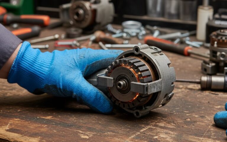
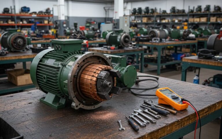
Q6. For repair markets, what’s the fastest way to judge whether a commutator is still “working” safely?
For quick triage, technicians often combine:
1. Visual check: bar colour, grooving, mica condition, copper drag.
2. Spark observation under representative load.
3. Basic measurements: commutator diameter, runout, and insulation resistance.
If sparking is heavy, bars are uneven, or mica is high, the commutator may be functioning electrically but is already a reliability risk, and grinding/refurbishment or replacement should be on the table.
Wrapping up
A commutator “works” when geometry, materials, magnetics, and duty cycle all line up so that current reversal happens quietly in a very small time window.
For a B2B buyer or designer, understanding that window — and the levers around it — is what turns a copper cylinder with slits into a controlled, predictable component in your drive system.