How Does a Commutator Work in a DC Motor?
If you’ve ever stared at a DC motor diagram and thought, “Okay, but what is that copper-bar thing really doing?” — this is for you.
Most articles say: “A commutator reverses the current every half turn so the motor keeps spinning.” True… but that’s like saying “lungs help you breathe” and stopping there. In this guide we’ll walk through what the commutator is, what problem it solves, and what’s happening in the coils millisecond by millisecond — in a way that you can visualize.
We’ll also peek into real engineering issues like sparking, armature reaction, and how designers fix them.
- TL;DR — The 10-second answer
- A DC motor has a coil (armature) in a magnetic field.
- Current in the coil creates forces that try to twist it (torque).
- Every half turn, the coil would naturally “fight back” and reverse torque unless you also reverse the current.
- The commutator is a rotating copper switch on the shaft that, together with stationary brushes, automatically flips which side of the coil is connected to + and – every half turn.
- This keeps the torque in the same direction, so the rotor doesn’t stall or vibrate; it just keeps spinning.
Table of Contents
1. Quick Refresher: What a DC Motor Is Actually Doing
At its core, a DC motor is just a current-carrying conductor in a magnetic field. According to Lorentz force, a conductor with current (I) in a magnetic field (B) feels a sideways force, and if that conductor is part of a loop, those forces become a torque that tries to rotate the loop.
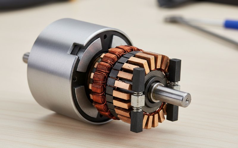
Inside a typical brushed DC motor, you have:
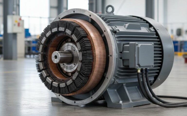
- A stator that provides the magnetic field (permanent magnets or field windings).
- A rotor/armature that carries the current and actually spins.
- A commutator + brushes that act as an automatic reversing switch, synchronised with the rotor position.
The magic is that the rotor never gets a chance to push backward — the commutator “flips the script” just in time.
- Key motor parts in one glance
- Stator – stationary part, holds the magnets/field windings that create the main magnetic field.
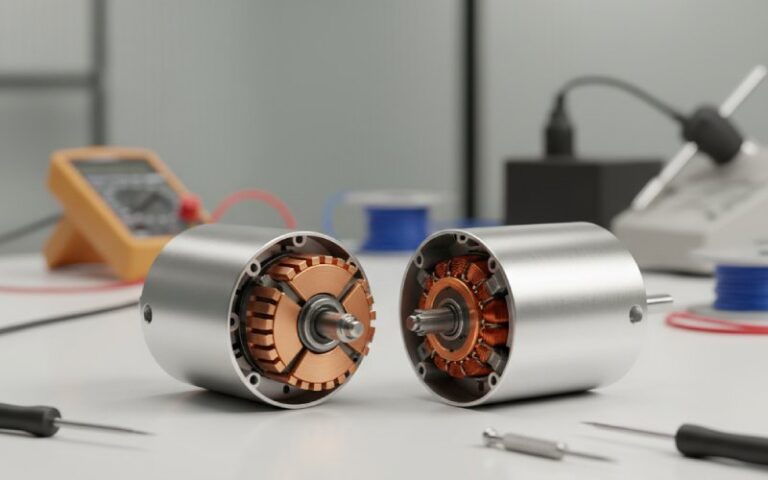
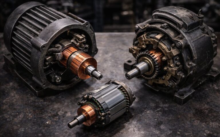
- Rotor (Armature) – rotating iron core with copper windings; this is where torque is produced.
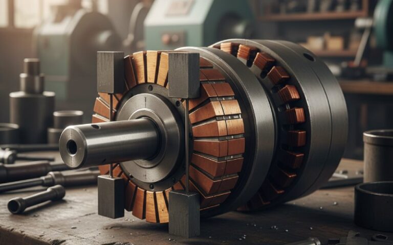
- Commutator – segmented copper ring on the rotor shaft; connects armature coils to the outside world and reverses current at the right moments.
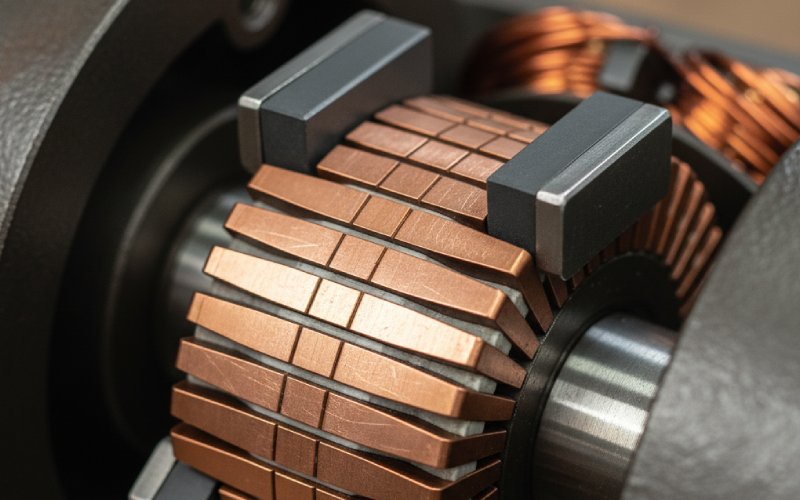
- Brushes – stationary conductive blocks (graphite/carbon or copper) that press on the commutator, carrying current in and out.
2. Meet the Commutator: The Motor’s Mechanical “Rotary Switch”
The commutator is literally a mechanical switch wrapped around the shaft.
It’s built as a cylindrical ring made of many copper segments, each segment insulated from the others (and from the shaft) by thin layers of mica. Each segment is connected to the end of one armature coil.
As the rotor spins, stationary brushes sit on this cylinder like shoes on a treadmill. They don’t move around the shaft; the commutator slides under them. By choosing where those segments are split and how they’re wired to the coils, we make sure that the coil that’s about to pass the “dead zone” has its connections swapped — plus and minus effectively change sides.
- What makes a commutator… a commutator?
- Segmented copper ring: multiple wedge-shaped copper bars forming a cylinder on the shaft.
- Insulation: mica or similar material between segments and between the ring and the shaft, so segments don’t short together.
- Connection to coils: each segment is tied to one end of an armature coil; the pattern of connections determines how current flows through the windings.
- Sliding contact with brushes: brushes are pressed with carefully adjusted spring force to maintain contact but limit wear and sparking.
3. The Real Problem the Commutator Solves
Imagine a simple single-loop motor: a rectangular coil sitting between two magnet poles.
When one side of the coil is under the north pole and the other under the south pole, the forces on the two sides push in opposite directions, creating a torque that spins the coil. Great. But now imagine that coil has turned half a revolution (180°).
- Without touching the connections, the current direction in the coil relative to the field is still the same.
- But the coil’s orientation is reversed.
- That means the forces on each side would reverse direction — your “push” becomes a “pull” and the motor would try to drive backwards or stall.
To avoid that, we want the current in the coil to flip exactly when the coil has rotated 180°. If we reverse the current at the same time the coil flips position, the forces stay pointing in the same physical direction, and torque keeps helping the rotation instead of fighting it.
That’s exactly the timing job the commutator + brushes perform.
- Without and with a commutator
- Without:
- Coil goes past 90°… torque drops.
- At 180°, forces reverse and try to push the rotor back.
- Result: oscillation or stall, not continuous rotation.
- With a commutator:
- Just as the torque would reverse, the connections are swapped.
- Current in the coil reverses; magnetic force directions stay helpful.
- Result: smooth, unidirectional torque and continuous rotation.
- Without:
4. One Full Turn: What the Commutator Is Doing at Each Angle
Let’s walk through one full revolution of a very simple DC motor with a two-segment split-ring commutator.
We’ll assume:
- Two brushes: one connected to +, one to –.
- One rectangular coil, its ends connected to the two copper halves of the commutator.
Rotor positions vs. commutator action
| Rotor position (simplified) | Which segment touches + brush? | Which coil side carries current out of the page? | Force on left side | Force on right side | Net effect |
| 0° – Coil horizontal | Segment A | Left side | Down | Up | Torque starts turning clockwise |
| ~90° – Coil vertical | Segment A (about to switch) | Left side (still) | Almost zero (coil edge-on) | Almost zero | “Dead zone”; coil coasts |
| 180° – Coil horizontal | Segment B (after swap) | Right side (current reversed through coil) | Down | Up | Torque still clockwise, motor keeps spinning |
| ~270° – Coil vertical | Segment B (about to switch) | Right side | Almost zero | Almost zero | Another dead zone |
| 360° – Back to start | Segment A again | Left side | Down | Up | Cycle repeats |
In reality, DC machines use many segments and many coils, so torque is much smoother than this very simple picture.
- How to picture this in your head (no diagram needed)
- Picture the coil as a rectangle: left side and right side.
- At 0°, left side is under the north pole, right side under the south pole. Current goes into the left side, out of the right side:
- Left side is pushed down, right side is pushed up → clockwise torque.
- As the coil reaches vertical (90°), it’s edge-on to the field, so forces drop — this is a natural “zero torque” point.
- At almost 180°, the coil would now try to produce torque the other way…
- But just before that, the commutator segments swap brushes: what used to be connected to + is now on –, and vice versa.
- That flip means current direction in the coil reverses, so the forces keep acting in the original rotation direction.
Try this: draw a rectangle, mark the current direction on the sides, then rotate the paper and flip the current arrows when the coil passes “vertical”. That’s basically what the commutator is doing mechanically.
5. Zooming In: The Commutation Interval and Sparking
The really interesting action happens during the tiny slice of time when a brush is bridging two commutator segments at once.
In that instant:
- The coil connected between those two segments is effectively short-circuited by the brush.
- The current in that coil must reverse from +I to –I during this short “commutation period”.
- Because the coil has inductance, it doesn’t like abrupt changes in current, so its own induced EMF can fight the reversal.
If the current doesn’t fully reverse by the time the segment leaves the brush, we get under-commutation — the old current direction is still partially present. That mismatch produces sparking at the brush–commutator interface, heats the copper, and wears it out.
Good commutator design and brush positioning try to ensure that:
- The coil is commutating when it’s near the magnetic neutral axis (where the net flux is minimal), so induced EMF and required current change are smaller.
- The timing of the mechanical contact aligns with the electrical need for reversal.
- Things that make commutation harder (and cause sparking)
- High current and inductance in the coil → more energy to flip, larger induced EMF resisting the change.
- Shifted magnetic neutral plane due to armature reaction (the armature’s own field distorts the main field).
- Wrong brush position (not aligned with the neutral axis at the operating load).
- Poor brush contact pressure – too light: unstable contact & sparking; too heavy: excessive wear and heating.
- Dirty or rough commutator surface, making current transfer erratic.
6. How Designers Help the Commutator Do Its Job
As DC machines got bigger and more heavily loaded, engineers had to get clever to keep commutation under control.
They use several tricks:
- Interpoles (commutating poles) Small auxiliary poles placed between the main poles, energized so they create a local magnetic field that helps the current in the commutating coil reverse more smoothly.
- Compensating windings Extra windings embedded in the pole faces, carrying current proportional to the armature current. These cancel out much of the armature’s own field (armature reaction), keeping the neutral axis stable across load conditions.
- Optimized brush material Carbon brushes are popular because they:
- Wear faster than copper segments (sacrificial, easier to replace).
- Have higher resistance, which slightly limits current spikes during commutation.
- Many small commutator segments More segments mean more coils in series around the circumference and smaller changes in current per coil, which smooths torque and makes each commutation step less violent.
- Practical design / maintenance rules often used in the field
- Keep brushes correctly positioned relative to the neutral plane for your typical operating load.
- Monitor brush wear, temperature, and commutator colour; unusual patterns often indicate commutation issues.
- Use the right brush material for your voltage and current levels (e.g., carbon vs copper).
- For high-power industrial DC motors, consider interpoles and compensating windings essential, not optional.
7. Commutator vs. Brushless: Why This Old Tech Still Matters
Modern systems increasingly use brushless DC (BLDC) and other electronically commutated motors. There, semiconductor switches play the role of the commutator, driven by a controller that knows rotor position (via sensors or back-EMF).
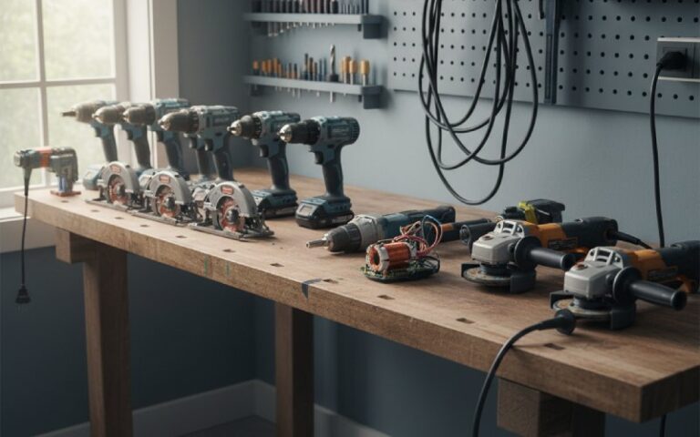
But brushed DC motors with commutators are still extremely relevant because they are:
- Simple to control (just apply DC voltage).
- Cheap to manufacture.
- Great for low-to-medium power, cost-sensitive applications (toys, power tools, small appliances).
In those motors, the mechanical commutator is literally the “controller in copper and carbon” — it bakes commutation logic into the hardware.
- Commutator DC motor vs brushless DC motor — quick comparison
- Commutator (brushed DC):
- Mechanical switching (commutator + brushes).
- More maintenance: brush wear, commutator cleaning.
- Very simple drive electronics (can be as simple as a battery + switch).
- Brushless DC:
- Electronic switching (inverter + controller).
- No brushes → less maintenance, higher lifetime, often higher efficiency.
- More complex and expensive electronics, but huge advantages in performance and reliability.
- Commutator (brushed DC):
8. Bringing It All Together
If you strip away the jargon, a commutator in a DC motor is a precisely timed, self-acting polarity flipper.
- It sits on the rotor shaft as a copper cylinder split into insulated segments.
- Brushes ride on it, feeding DC into a rotor whose coils constantly move under the magnet poles.
- As each coil passes the position where torque would reverse, the commutator quietly swaps which segment touches which brush, so current direction in that coil flips exactly when its geometry flips.
- Deep inside that moment, commutation is a race between inductance, induced EMF, and clever motor design; when it’s done right, all you see is a shaft spinning smoothly.