Handling High-Speed Rotation: Balancing and Centrifugal Forces in Commutators
High-speed rotation makes commutators weird.
On paper the rotor balances. The FEM plot looks fine. Then someone runs the drive at 3,000 rpm more than usual and calls you about noise, brush dust, or a comm bar that’s suddenly running hot. That’s the gap this article tries to close: not the textbook, but the “why is this real machine misbehaving?” side of high-speed commutators, balancing and centrifugal forces.
You already know the physics and the standards. So let’s stay close to what matters in B2B projects: design choices, tolerances, process control, and what to ask your commutator supplier for when speeds start to climb.
Table of Contents
1. High-speed stress on commutators is not just a math problem
Once peripheral speed goes up, the commutator stops being a quiet copper ring and starts behaving like a stressed rotating shell.
Typical issues that show up first:
- Segment movement and loosening
- Centrifugal loading tries to peel segments away from the hub and from each other.
- Traditional V-ring designs only go so far before steel or glass banding becomes mandatory to keep segments from walking out under load.
- Radial deformation under thermal plus centrifugal load
- High surface speed → more frictional heating at the brush track → copper and support structure expand unevenly.
- That distortion shows up as increased inter-segment step, local high bars, and higher sparking levels, which then shorten life.
- Brush contact quality collapsing at one specific speed band
- At certain speeds, small unbalance and geometric errors line up with contact resonance of the brush gear.
- Result: brush bounce, commutator bar streaking, unexplained film patchiness.
- Invisible machining and assembly sins becoming loud
- Concentricity that was “good enough” at 1,500 rpm suddenly drives arcing at 5,000 ft/min surface speed; recommendations around 0.001″ TIR at ~5,000 ft/min and tighter above that aren’t there for fun.
If your site sells or integrates commutators, this is a good framing for buyers: high-speed operation is not just higher rpm; it’s a different failure profile.
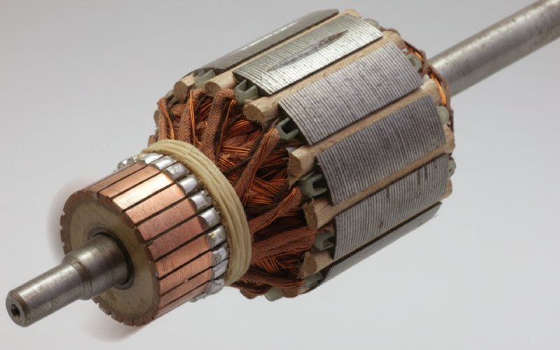
2. Centrifugal forces inside the commutator stack
You already know the formulas. In practice, what matters is where those forces actually land.
- Segments and support rings
- Copper segments see hoop stress plus bending at the dovetail or undercut.
- V-rings, shrink rings, or banding take the radial load and transfer it into the hub. At higher surface speeds, designs shift toward glass- or steel-banded commutators specifically to keep segments clamped under rising centrifugal forces.
- Insulation system (mica, resin, slot fillers)
- Mica and resin carry part of the shear between segments; overheating at high speed weakens these layers and you start to see inter-segment movement rather than a simple “roundness” issue.
- Once that happens, no amount of balancing fixes the root cause; you are chasing geometry that changes with load.
- Interface to the armature core
- Many manufacturers assemble the commutator with the armature already in place to manage mechanical stress distribution and concentricity along the full stack.
- If your rotor has the commutator pressed on later, misalignment between bearing seats, core, and commutator bore shows up as speed-dependent runout at the brushes.
When you read balancing data, remember: the balancer sees the sum of all these effects as a simple unbalance vector. But the corrective drill or clip is compensating for the mechanical stack-up inside the commutator as much as the iron.
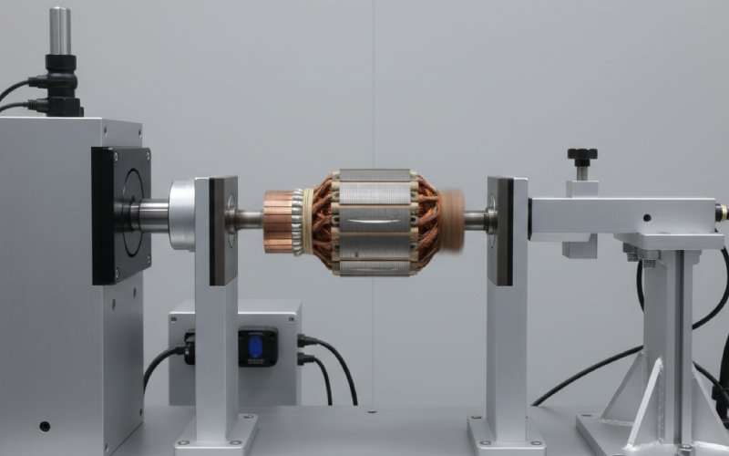
3. Balancing strategy for commutator rotors
Balancing has its own theory sections in every manual. The interesting part is: what actually works for a commutator rotor running fast.
3.1 Rigid vs. flexible behaviour in real machines
- Rigid region
- As long as the rotor behaves rigidly, you can balance at a fraction of service speed, provided there’s enough centrifugal force for the sensors to see the unbalance clearly.
- Approaching or crossing a critical speed
- Once the rotor flexes, you’re not balancing “the rotor” anymore; you’re balancing shape modes. That means multiple correction planes and staged speeds.
For high-speed commutator machines, it’s common that:
- The armature itself is still almost rigid.
- The commutator plus shaft extensions plus coupling push the assembly into more flexible behaviour.
So treating it as a simple two-plane rigid rotor sometimes hides the problem.
3.2 Does balancing speed matter?
Short answer: yes, but not in a mystical way.
- Higher balancing speed increases the centrifugal force for a given residual unbalance, which helps sensitivity and accuracy of the balancer.
- Balancing too far below service speed can miss speed-dependent deformation and fit issues (rings opening up, commutator hub creeping).
- Balancing too close to service speed on an under-rated rig means you’re using the balancer as an overspeed tester, which isn’t its job.
For a B2B commutator supplier, one useful thing to publish:
- Your balancing speed band vs. rated operating speed, especially for long or high-inertia rotors.
4. Setting realistic limits: surface speed, runout, vibration
The official documentation gives numbers. Real plants add “how much risk are we willing to carry” on top.
A few patterns you see across literature and field data:
- Many traditional DC machines operate around 30 m/s commutator surface speed as a comfortable limit for standard designs; pushing toward 45 m/s is possible with more maintenance and tighter control.
- High-performance brush and ring systems run above 35 m/s when materials and cooling are chosen for that duty.
- At ~5,000 ft/min (~25 m/s) and above, concentricity requirements go down into the 0.001″ TIR range or better at the commutator track; above ~9,000 ft/min, recommended TIR halves again.
So when someone asks “Can we increase the base speed by 20 %?”, the mechanical answer is not just thermal. It’s:
- Does the surface speed stay in a band that your commutator construction and brush grade can tolerate?
- Can your existing runout and vibration targets support that speed without crossing the sparking threshold?
A good practical way to frame limits internally:
- Surface speed band (m/s or ft/min).
- Max acceptable vibration at bearing housings (mm/s).
- Max TIR at commutator OD.
- Max segment step across the track.
That combination aligns with how failures actually show up: as vibration plus sparking plus uneven film, not as a neat unbalance number.
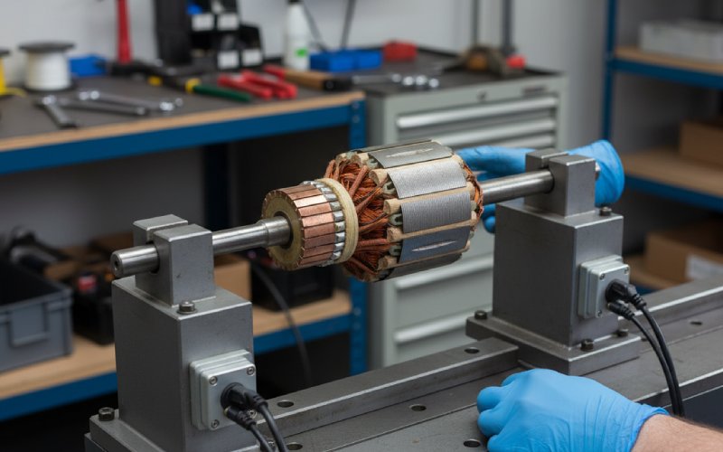
5. Manufacturing and test routines that actually catch problems
If you want a high-speed commutator rotor that behaves in the field, three areas usually matter more than another paragraph of theory.
5.1 Machining and finishing
- Turn the commutator in one set-up with the bearing seats whenever possible. That keeps the electrical track concentric to the mechanical axis that matters.
- Target a surface finish in the typical 1–1.5 µm Ra band (40–60 µin) or as per your brush supplier, and verify after any re-true operation.
- Protect mica edges and banding, especially when refinishing in place; contamination there later contributes to tracking and uneven heating.
5.2 Balancing workflow
For high-speed commutator rotors, a workable pattern:
- Pre-balance the bare armature (without commutator) near rigid-body speed.
- Assemble commutator and banding, then run a second balancing step on a more realistic mandrel or the actual shaft.
- Final balance with fan, coupling pieces, and any shrink-on rings installed, at a speed high enough to see real-world deformation but within safe limits.
This avoids hiding commutator-induced unbalance inside “armature scatter”.
5.3 Overspeed and thermal checks
Mechanical docs will define overspeed factors. In practice:
- A short overspeed run (to the qualified factor) verifies the commutator’s banding, dovetails and hub fits under centrifugal load.
- A separate thermal run at high load validates that the combination of brushes, cooling and commutator design doesn’t push segments into a creep zone.
Publishing these test steps on your product pages quietly answers a lot of buyer questions about reliability at speed.
6. Field signals that your high-speed commutator is unhappy
Here’s a compact view you can reuse in internal docs or on your site.
Typical high-speed commutator symptoms and actions
| Symptom at high speed | Likely mechanical / centrifugal cause | Checks and actions that actually help |
|---|---|---|
| Vibration rises sharply in a narrow speed band, then drops again | Rotor near a critical speed; flexible behaviour not covered in balance | Plot vibration vs. speed, re-balance at multiple speeds, add plane near commutator or coupling |
| Brushes spark mainly on one quadrant of the commutator | Runout or segment step amplified by centrifugal deformation | Measure TIR hot, check banding and hub fits, re-true commutator, verify bearing fits |
| Uniform vibration increase with speed; no strong resonance | Simple mass unbalance or eccentric commutator | Dynamic balance with commutator installed, confirm concentric turning with shaft seats |
| Brush wear rate jumps after a speed uprate | Surface speed beyond brush / commutator design band | Confirm surface speed vs. supplier limits, review brush grade and cooling, consider reinforced commutator construction |
| Random flashovers after long high-speed runs | Thermal growth and weakened insulation, segment movement | Infrared survey, check inter-segment insulation, inspect banding, review duty cycle and load |
| Audible “hammering” or chatter from brushgear at speed | Brush bounce from combined vibration and poor concentricity | Verify commutator roundness, spring pressure, brush overhang, and bearing condition |
| Repeated balancing corrections never seem to “stick” | Internal mechanical stack shifting under load | Inspect commutator hub fit, banding tension, and shaft shoulders; consider redesign of commutator support |
You can adapt this table straight into a troubleshooting page on your site with your own test data and limits.
7. How this ties back to commutator selection for B2B projects
If you’re specifying or selling commutators into high-speed DC drives, a practical checklist to share with customers:
- Construction
- V-bound, glass-banded, shrink-ring design? Up to what surface speed has that specific construction been qualified?
- Balancing and test data
- Stated balancing speed, balance quality grade, and how many correction planes.
- Whether the commutator is balanced as part of the full rotor assembly.
- Geometric tolerances at speed
- Concentricity and runout numbers for the commutator track at rated speed bands.
- Thermal and brush system compatibility
- Brush grades and current density vs. surface speed capability.
- Cooling concept around the commutator (fan design, air paths, screens).
Making this information visible on a B2B site often does more for serious buyers than generic “high reliability” claims. They already know what failures cost them.
FAQ: High-speed rotation, balancing and commutators
1. How fast can a commutator safely run?
There isn’t a single universal number.
For many traditional DC machines, around 30 m/s surface speed is treated as a comfortable limit for standard commutator and brush systems. With better materials, reinforced banding and more maintenance, designs operate in the 35–45 m/s range and above.
The safe answer for any project is:
Ask for the qualified surface-speed range of that exact commutator construction.
Match it with brush data (current density vs. surface speed) and the thermal design of the machine.
2. Is balancing at low speed good enough for a high-speed rotor?
Sometimes yes, sometimes no.
For truly rigid rotors, balancing at a lower speed is fine as long as the sensors see enough centrifugal force for decent resolution.
For rotors that approach a critical speed or show flexible behaviour, you need staged balancing at multiple speeds and correction planes.
If a machine runs smoothly until a specific speed band and then becomes noisy, that’s a hint the balancing speed was not representative.
3. Why do high-speed machines use glass- or steel-banded commutators?
Because at high surface speed, centrifugal forces try to throw the segments off the hub.
Glass or steel banding wraps the commutator with a high-strength hoop that keeps segments clamped in place, beyond what V-rings alone can carry. High-frame DC motors and traction drives often combine V-rings with glass banding down the centre of the commutator for this reason.
4. Can balancing fix sparking caused by commutator deformation?
Balancing can reduce vibration, which sometimes lowers sparking indirectly. But if the root cause is radial deformation, inter-segment step or creeping insulation due to thermal and centrifugal stress, balancing is just cosmetic.
You’ll need to address:
Commutator construction and banding
Operating temperature and cooling
Brush grade and loading
before the problem really goes away.
5. What should I publish on my commutator product pages to satisfy high-speed buyers?
Engineers shopping for high-speed commutators usually look for:
Clear surface-speed and current-density limits for each design family.
Construction description (V-bound, glass-banded, shrink-ring) and tested overspeed factors.
Balancing quality, balancing speed, and test procedures used.
Recommended tolerances for runout, concentricity, and surface finish, tied to speed ranges.
Those details let them compare suppliers quickly without another email thread.