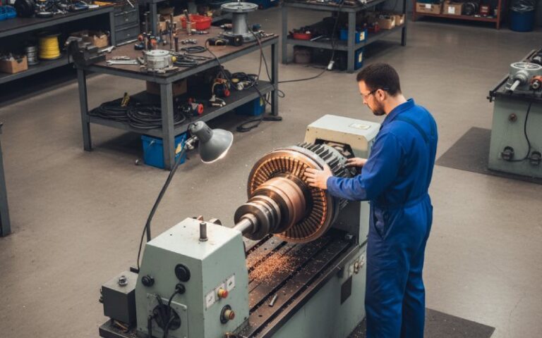
Function of Split Ring Commutator in an Electric Motor
This article looks at the function of the split ring commutator in a DC electric motor from an operations, reliability, and sourcing angle.
Table of Contents
1. Short Answer: What the Split Ring Commutator Actually Does
At its core, the split ring commutator is a mechanical switching interface on the rotor that:
- Periodically reverses armature current as the rotor turns, so torque keeps a roughly constant direction.
- Acts as a mechanical rectifier between the DC supply and the rotating windings, shaping what would otherwise be an alternating current in the armature into a usable form at the terminals.
- Provides a sliding contact surface for brushes, combining electrical function (switching) with mechanical constraints (rotation, misalignment, vibration).
On paper, that’s it. In the field, the same part quietly sets limits on speed, noise, maintenance intervals, and even whether your product passes EMC and safety testing on schedule.
2. Why Current Reversal Matters Beyond Textbook Diagrams
Documentation usually says:
without the split ring, the coil would rock back and forth instead of rotating continuously.
That’s the student version. For a business, the real consequences look more like this:
- Torque continuity The commutator keeps the electromagnetic torque mostly in one angular direction. When commutation is poor, you see torque ripple. On your side this shows up as audible noise, vibration in geartrains, and customer complaints about “rough running” at low speed.
- Startup reliability The way the segments are oriented relative to the armature slots decides how much starting torque you get in unlucky rotor positions. On a drawing it’s a small offset. On a production line it’s the difference between “motor starts every time” and “tap the housing and try again”.
- Direction control Reversing supply polarity changes the direction of current through the commutator and hence the direction of rotation. That simple behavior underpins H-bridge control in many DC drives. Without consistent commutator behavior, reversing logic becomes messy.
So yes, it reverses current each half turn. But what you really buy is predictable torque and direction under real loads, over many cycles.
3. The Split Ring’s Business-Facing Functions in One Table
Here’s a compressed view that’s more sourcing-friendly than a field diagram.
| Physics-level function of the split ring commutator | Design / engineering knob | Business impact when you get it wrong |
|---|---|---|
| Reverses armature current each half rotation to maintain torque direction | Segment geometry, brush width, brush offset | Strange low-speed behavior, torque dead-spots, product returns |
| Acts as mechanical rectifier between rotor and external DC circuit | Number of segments, armature winding pattern | Voltage ripple, EMI issues, test failures |
| Provides sliding electrical contact via brushes | Brush material, spring force, surface finish | Excessive sparking, brush dust, shortened service life |
| Shapes commutation interval where current transfers between segments | Inter-pole design (if any), neutral plane setting | Heating, local burning of segments, unexpected downtime |
| Maintains insulation between segments at high speed and temperature | Insulation material (mica, polymer), slot design | Shorted segments, catastrophic failure under overload |
If you manage motors as components in a larger product, this is the level worth tracking in specs and supplier reviews.
4. Inside the Function: What Changes When You Change the Commutator
The function stays “reverse current, keep torque direction stable.” How it performs that function shifts a lot with design choices.
4.1 Segment count
Higher segment count:
- Shorter electrical angle per segment
- More frequent but smaller current transfers
- Smoother torque and lower electrical noise, at the price of complexity and cost
Lower segment count:
- Larger current steps
- More torque ripple and commutation stress
- But cheaper, easier to manufacture, often fine for low-duty or cost-sensitive products
Same function, different risk profile.
4.2 Materials and surface
Common pattern you see:
- Copper-based segments for conductivity and machinability.
- Mica or engineered polymers as segment insulation.
- Carbon or graphite brushes to control wear and contact resistance.
From a “what does it actually do” standpoint:
- Softer brush materials protect the commutator surface but create more dust.
- Harder brushes reduce dust but can score segments.
- Both change how the current reversal zone behaves under load. Same function, altered lifetime and noise signature.
4.3 Geometry and neutral plane
The split ring isn’t just a ring cut in half. Segment edges, skew, and alignment with the armature slots decide:
- How long a coil remains shorted under a brush during commutation.
- At which mechanical angle the current swaps sign in that coil.
If your supplier adjusts this and doesn’t tell you, you may suddenly see:
- Improved performance at one operating point but worse at another.
- Different EMI fingerprint, even with the same nominal ratings.
The function stayed identical. The side effects shifted.
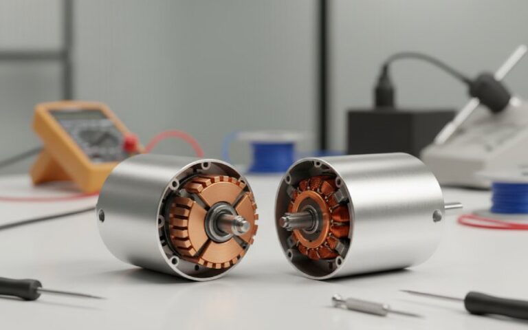
5. Split Ring vs Slip Ring vs Electronic Commutation
The split ring commutator is often confused with slip rings. They are not interchangeable.
- Split ring commutator Segments are insulated from each other and connected to different coils. The brush position defines which segment is energized and in what direction. Result: built-in current reversal and torque direction control for DC motors.
- Slip rings Continuous rings, typically one per phase, used mainly in AC machines. They pass whatever waveform you supply (or generate) without intentional reversal. The torque direction is then controlled electronically or by the external circuit.
- Electronic commutation (brushless DC motors) No split ring. Rotor usually holds permanent magnets, and semiconductor switches do the current reversal based on rotor position feedback. The classic split ring function is replaced by firmware and silicon.
From a B2B standpoint:
- Split ring: simple drive electronics, more mechanical wear.
- Slip ring + AC: more infrastructure (inverter, control), fewer wear parts.
- Electronic commutation: higher component count, but predictable performance and easier EMC tuning.
You’re not just choosing a part. You’re choosing where the “commutation function” lives: metal, carbon, or code.
6. Failure Modes That Quietly Reveal the Commutator’s Function
When the function degrades, symptoms show up in ways that rarely mention “current reversal” in the failure report.
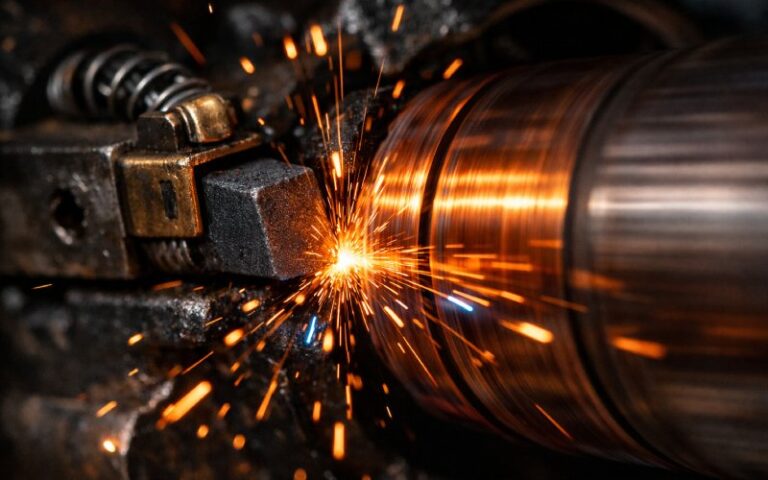
6.1 Excessive sparking at the brushes
Signs you might see:
- Bright orange arcs at nominal load
- Discoloration of a few commutator segments only
- Audible crackling
Possible functional causes:
- Commutation interval too short or shifted; current doesn’t decay cleanly before the brush leaves a segment.
- Brush spring pressure wrong, so contact is intermittent at certain angles.
- Surface contamination changing contact resistance.
Your function statement “ensure smooth reversal of current” is not being met under the real operating waveform.
6.2 Uneven wear pattern
If the commutator is doing its job unevenly, the metal will tell you:
- High ridges or grooves aligned with specific segments
- Brush wear concentrated on a narrow width, not the full track
- Periodic noise at a frequency tied to rotor speed
Typical chain:
- Design / setting shifts the practical neutral plane.
- Commutation runs “off-center” in electrical terms.
- Some segments carry more stress.
- Function still exists, but with local overload that shortens lifetime.
6.3 Thermal issues
Because the commutator is the region where current changes direction, it is also where resistive losses and switching losses stack up. Poor function shows as:
- Local hot spots on thermal camera images
- Smell of heated insulation after repeated start-stop cycles
- Degradation of insulation between segments over time
Again, same theoretical function. Different thermal margin.
7. How to Talk About Split Ring Function in a Specification
If you just state:
“Motor must have split ring commutator.”
…you leave a lot of performance on the table.
More practical handles to include:
- Target lifetime in starts/stops and operating hours The supplier can then tune brush grade and segment finish accordingly.
- Typical operating profile Long steady runs, or frequent reversals, or PWM speed control at low duty? Each stresses the commutation function differently.
- Acceptable noise and vibration envelope If your product has tight acoustic requirements, torque ripple from commutation may be a constraint.
- EMC expectations If there is strict conducted or radiated emission testing, the way current is reversed at the split ring matters. Supplier might propose higher segment count or additional filtering.
Instead of only buying “a commutator,” you’re buying a way of reversing current that fits your product context.
8. Practical Checklist Before You Approve a Motor Sample
Even without cutting the motor open, you can infer whether the split ring function is aligned with your needs:
- Low-speed behavior
- Slowly ramp from standstill to low speed under light load.
- Watch for dead angles, stick–slip motion, or strong speed ripple.
- Reversing test
- Alternate direction changes under realistic load.
- Check whether sparking increases just after each reversal, or stays stable.
- Thermal soak
- Run at nominal load until temperature stabilizes.
- Power off, then inspect around the brush/commutator area for discoloration or odor.
- Brush inspection after a defined number of cycles
- Look for even contact pattern.
- Check that dust build-up is manageable given your enclosure and filters.
- Basic EMI scan (if possible)
- Even coarse near-field probing can show whether the commutation function is generating bursts at certain angles.
All of this traces back to a single line: how the split ring commutator is reversing current in practice, not just in the drawing.
9. FAQ: Function of Split Ring Commutator in Electric Motors
Q1. Is the split ring commutator only about reversing current?
No. Reversing current is the headline role, but in operation it also:
Sets the timing of that reversal.
Defines the interface quality between brushes and armature.
Influences noise, lifetime, and EMI even when the circuit diagram stays the same.
Q2. Why can’t we just use slip rings and supply DC?
You can physically connect DC via slip rings, but slip rings do not switch polarity for each coil in sync with rotor position. You would either:
Get oscillating torque, not continuous rotation; or
Need external electronics to imitate what the split ring does mechanically.
The whole point of the split ring is that mechanics and geometry handle the timing.
Q3. How does the number of commutator segments affect function?
More segments:
1. Shorter switching intervals
2. Smoother torque and lower current spikes
3. Higher manufacturing cost and more complex assembly
Fewer segments:
1. Larger current jumps during reversal
2. More stress per segment and possibly more sparking
3. Simpler mechanics
Functionally identical at the schematic level, different behavior under real loads.
Q4. What happens if one segment is damaged or shorted?
Depending on the fault:
Open segment: the associated coil might never get energized correctly, causing torque ripple and possibly a “bump” in each rotation.
Shorted segment or bridging between neighbors: current paths change, local heating occurs, and the function “clean current reversal at defined angle” breaks down.
You still have a rotating motor, but with lower efficiency, higher stress, and poor predictability.
Q5. How does brush material change the commutator’s function?
Brush material affects:
1. Contact resistance
2. Film formation on the copper
3. Wear rate of both brush and segment
The functional core—reversal of current—remains, but:
1. Too hard a brush: switching occurs with higher contact noise, higher local heating.
2. Too soft: function remains stable but lifetime and dust output worsen.
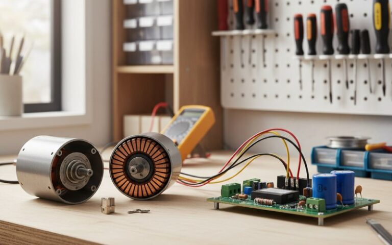
Q6. Do brushless DC motors make the split ring commutator obsolete?
Brushless designs move the commutation function into electronics. No brushes, no split ring. But there are trade-offs:
Higher component count and control complexity
Different failure modes (sensors, drivers, firmware)
Often better controllability and efficiency for variable-speed drives
For many cost-sensitive, low-voltage applications, the mechanical split ring solution still hits a useful balance between simplicity and acceptable maintenance.
Q7. If my motor’s datasheet already says “DC motor with split ring commutator”, what extra should I ask?
For industrial or high-volume use, consider asking for:
Expected brush life at your load profile
Maximum recommended current ripple on the supply
Typical spark level classification
Any limitations on PWM frequency or duty cycle for speed control
All of these relate directly to how the split ring commutator carries out its switching function inside the motor.