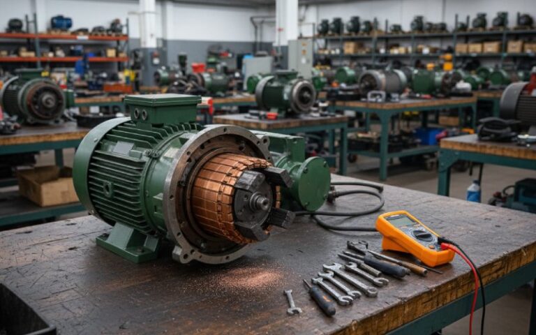
Electric Motor Commutator Repair: How Serious Shops Actually Do It
Electric motor commutator repair sits in an odd spot. Too simple in the manuals. Too easy to ruin in the field.
What usually matters is how to decide repair vs replace, how to control the machining and undercutting work, and how to prove the commutator will survive the next outage cycle.
This guide focuses on that. Process, numbers, and failure patterns.
Table of Contents
1. When is electric motor commutator repair the right choice?
Replacement sounds clean. In practice it means long lead times, re-qualification, and a different risk profile. So most plants push for repair first.
Typical indicators that repair is still realistic:
- Diameter is above the minimum OEM data sheet or maintenance spec usually lists a minimum commutator diameter. Below that, bar support and mechanical strength drop off and you’re only buying a short extension of life. Some repair specs also limit total material removal per life cycle and define a minimum diameter for further turning.
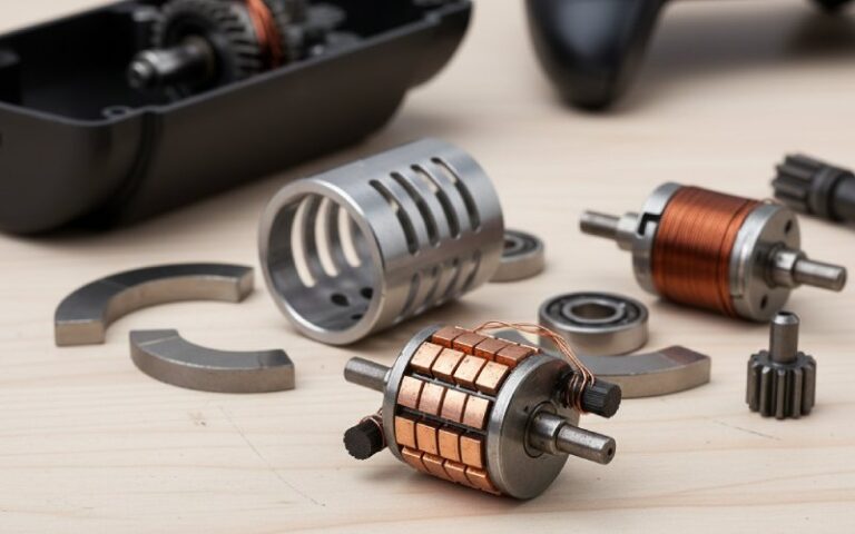
- Bars are structurally sound and tight Bars must still be firmly locked to the vee rings with no signs of lift, cracked silver solder, or loose risers. Industry repair specs require bars to be securely held and call for AC tests between bars and to ground on stripped commutators to verify integrity.
- Damage is surface-level or geometric, not metallurgical Grooving, bar edge burning, flat spots from overload, uneven filming, light streaking — these are usually repairable with turning, undercutting, and the right brush changes.
- Armature and windings can still pass electrical tests If bar-to-bar resistance, surge tests, and hipot indicate local faults only, you can often repair the commutator and leads instead of rewinding the entire armature.
Red flags where you stop talking about “commutator repair” and start talking about “new armature”:
- Bars mechanically distorted from severe standstill load or flashover (copper annealed, arch pressure pushed them out permanently).
- Multiple broken commutator leads or stabilizing windings with thermal damage into the armature slots.
- Deep cracks in the commutator shell or vee rings.
- Diameter already at or near the minimum allowed by OEM or repair spec.
The business rule many plants quietly use: if you can restore geometry, insulation, and surface condition while keeping clear margins to the minimum diameter, repair is usually worth it. If not, stop cutting copper.
2. What proper electric motor commutator repair actually looks like
Every shop has its rituals. Good ones still share a backbone.
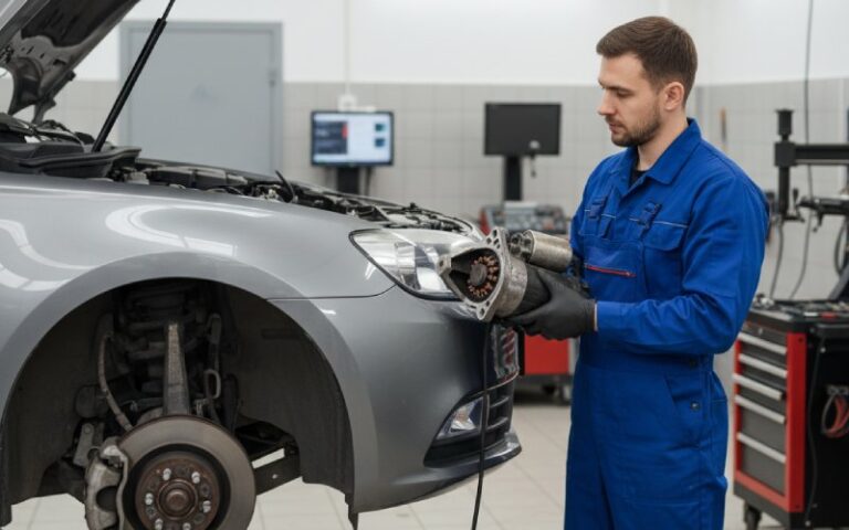
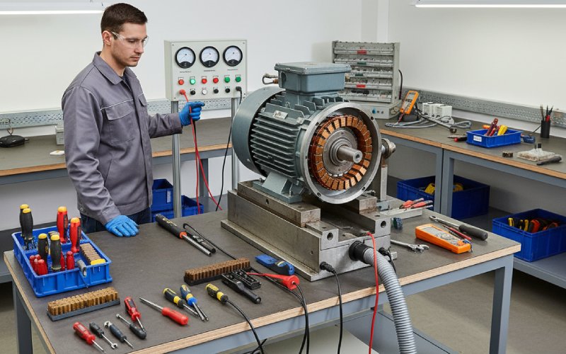
2.1 As-received tests and documentation
On a healthy repair job, no one rolls the motor straight onto the lathe. A typical industrial procedure looks like this:
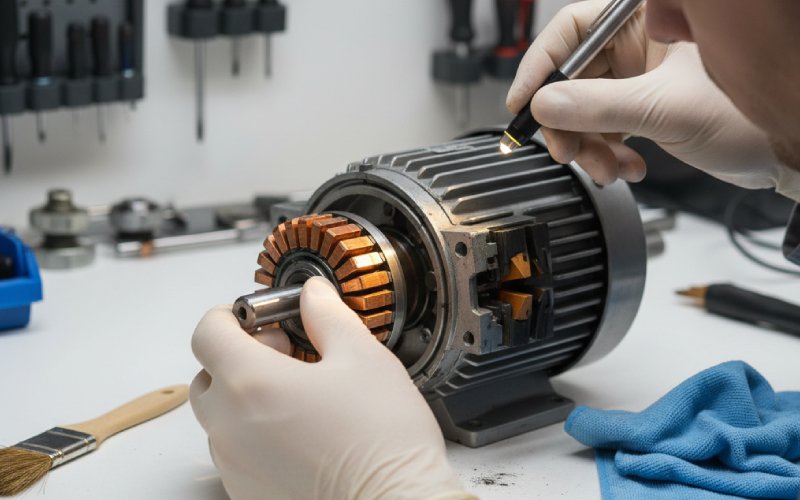
- As-received inspection
- Photograph brush gear, lead dress, commutator condition.
- Note wear patterns, bar burning, colour of film, and any evidence of tracking.
- Record spring pressure and brush grade; wrong brush material is a classic root cause for grooving and streaking.
- Incoming electrical tests
- Insulation resistance and polarization index.
- Bar-to-bar tests or voltage-drop tests on the commutator.
- Surge or pole-drop testing where applicable.
- Run test before tear-down (if safe) If the machine will run, it is usually driven to rated speed under light load to record vibration, sound, and brush sparking levels. That behaviour tells you whether you are dealing mainly with commutation issues or deeper mechanical problems (bearings, shaft, couplings).
This data is not “nice to have”. It keeps later disputes grounded when the motor returns to service.
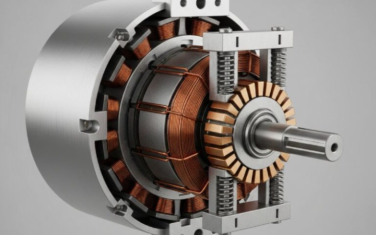
2.2 Turning / skimming: restoring geometry, not just looks
A commutator that is out-of-round or lobed will chew through brushes and encourage arcing even if the electrical design is perfect. Many maintenance articles highlight roundness as one of the main conditions for stable commutation.
Typical shop practices:
- Total indicated runout Industrial repair specs often call for maximum commutator runout of about 0.002″ (0.05 mm) on the finished surface for many sizes, measured with a dial indicator.
- Minimum diameter Commutator can only be skimmed down to a limit specified by the OEM or repair standard. Once reached, further machining should stop and replacement planned.
- Cutting practice Sharp tool, large nose radius, relatively high surface speed, and light feed. This avoids tearing the copper and keeps the bar edges solid enough for later undercutting. Machinists often treat copper similar to soft aluminium but watch chip formation and vibration even more closely.
The target is a clean cylindrical surface, no ridges, ready for undercutting.
2.3 Undercutting and deburring: where many shortcuts happen
Mica will not wear the way copper does. Leave it proud and the brushes will ride on insulation instead of copper; that gives you poor current sharing, arcing, and eventually bar edge burning.
Good practice typically includes:
- Depth Several published specs and training materials call for undercut depths in the range of 1/16″ to 3/32″ (about 1.6–2.4 mm) below the bar surface, or about 0.050″ in some DC motor guides. Enough for clearance, but not so deep that the bar edges become fragile.
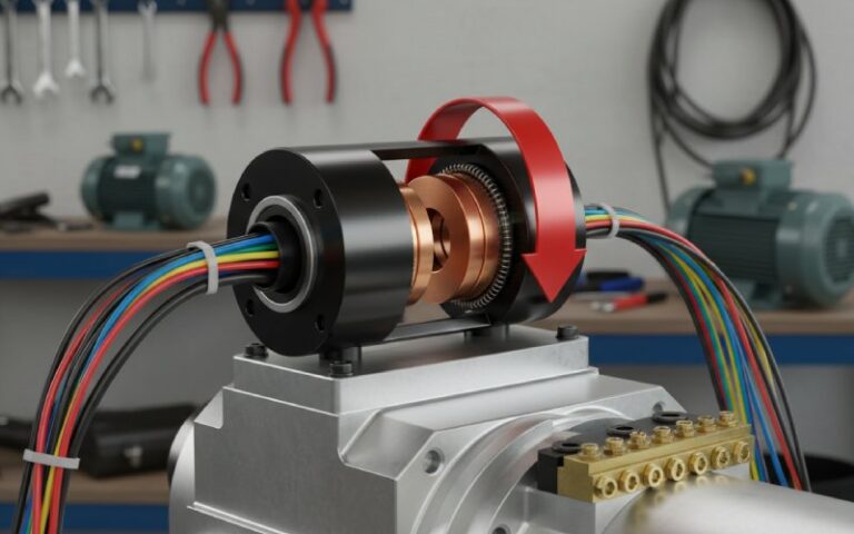
- Consistency Automatic undercutting equipment with floating heads is commonly used for larger machines to keep the slot depth uniform and follow small runout variations without gouging.
- Deburring and chamfering After cutting, burrs on bar edges must be removed and corners lightly chamfered. Some refurbishment systems combine undercutting, stoning, and chamfering devices in one sequence to keep geometry aligned and avoid leaving sharp edges that promote filming problems or brush chipping.
Skipping proper deburring is one of the quickest ways to ruin an otherwise good machining job.
2.4 Stoning, polishing, and brush seating
Once turning and undercutting are finished:
- The surface is usually stoned with a commutator stone, not generic sandpaper, to remove tool marks and minor high spots while preserving roundness.
- Any conductive dust or copper particles are removed from the slots.
- Brushes are refitted and seated on the new surface; this might use special seating stones or bedding procedures to establish full contact.
Using ordinary sandpaper can leave abrasive particles that embed into the copper and raise wear rates, which is why many maintenance instructions explicitly warn against that approach.
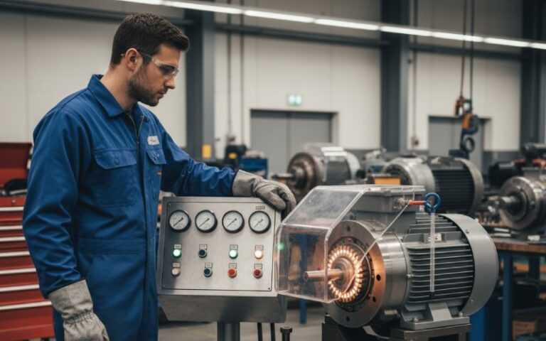
2.5 Electrical and mechanical tests before release
A repaired commutator should not leave the shop without a batch of checks:
- Bar-to-bar test or “growler/voltage drop” to confirm no local shorts or opens.
- Insulation resistance and hipot to ground and between windings.
- Runout and diameter measurements recorded and filed.
- Balancing of the armature if enough material was removed to affect mass distribution.
The better shops keep these for many years, aligned with long-term repair record requirements in some industrial standards.
3. Common commutator damage patterns and how repair responds
A lot of commutator troubleshooting guides list defects, but they stop at “check brush pressure” or “inspect interpoles”. Let’s push it a little more toward decisions you actually need to make during electric motor commutator repair.
| Visible condition on commutator | Likely root causes (short version) | Checks you run | Typical repair action | System fixes to prevent repeat |
|---|---|---|---|---|
| Bar edge burning at trailing edge | Poor commutation: wrong brush grade, incorrect neutral setting, incorrect interpole strength, uneven current sharing. | Verify brush type vs OEM, check neutral with minimum sparking method, inspect interpole connections, compare current distribution. | Turn commutator, undercut, deburr; replace brushes if grade is unsuitable. | Re-set brush gear, verify field and interpole circuits, adjust spring pressure to spec. |
| Regular burn marks every few bars or pitch bar burning | Broken commutator leads, shorted armature coils, commutating pole issues. | Bar-to-bar testing, surge test, inspect risers and leads, thermal evidence on windings. | Often demands repair or replacement of leads or a rewind; commutator machining alone is not enough. | Review overload history, start/stop duty, protection settings. |
| Smooth grooving around circumference | Abrasive dust in atmosphere; overly abrasive brush grade; insufficient brush pressure. | Check environment (cement, carbon, mineral dust), examine brush material and wear pattern, measure spring pressure. | Turn commutator to remove grooves; undercut and deburr; fit correct brush grade. | Improve sealing and filtration, adjust brush pressure, change brush material. |
| Flat spots / out-of-round after overload or locked rotor | Standstill load in one position, thermal softening of copper, arch pressure pushing bars outward permanently. | Cross-check event history (jammed load, start attempts), look for local colour change, compare diameter at multiple positions. | Light turning may fix; heavy damage may force commutator replacement. | Limit standstill load duration, update protection to avoid repeated blocked starts. |
| Loose or “drummy” bars | Thermal cycling, insufficient tightening during original manufacture or previous repair, corrosion at vee ring joints. | Tap test with light hammer, feel for bar movement, inspect vee rings and soldered joints. | Depending on design: re-staking, brazing, or full commutator strip and rebuild. | Review load cycling, vibration levels, storage and moisture conditions. |
This kind of matrix is usually where repair work earns its pay. Most defects ask for a combined response: machine copper and change something in the system.
4. What to ask from a commutator repair partner (B2B view)
If you are outsourcing electric motor commutator repair, you don’t need the shop’s trade secrets. You do need evidence that their process matches modern industrial practice.
Questions that filter shops quickly:
- What runout and undercut tolerances do you work to, and how do you prove them? Look for numeric answers, e.g. “0.002″ TIR on the commutator” or similar, aligned with industry guidance.
- Do you use dedicated commutator lathes and automatic undercutting equipment for larger machines? Automated systems with floating heads, integrated deburring, and controlled slot depth are standard in many serious DC motor rebuild facilities.
- Which incoming and outgoing tests are recorded? Expect at least: insulation resistance, bar-to-bar tests, mechanical measurements, and an as-run test where practical.
- How long do you keep repair records and measurement sheets? Some specs call for records to be archived for more than a decade. Shops that keep data that long usually operate with structured procedures rather than improvisation.
- What brush suppliers and grades do you usually pair with your commutator work? Having a view on brush grade, film behaviour, and wear patterns indicates familiarity with commutator surface conditions, not just copper cutting.
You are essentially checking that their process goes beyond “turn, undercut, and ship”.
5. Five on-site shortcuts that make commutator repair harder later
People try to “help” a commutator in the field. Sometimes it just makes the eventual shop repair more expensive.
- Aggressive sanding with standard abrasive paper Common, quick, and not recommended. Abrasive grains can embed into the copper and cause abnormal wear and filming issues. Several guides advise against generic sandpaper for exactly this reason.
- Skimming without undercutting high mica Even a small amount of proud mica will push the brushes off the copper, raise contact resistance, and create bar edge burning. Proper undercutting is part of the same job, not an extra.
- Resetting brush holders by eye only Brush gear can drift. Without checking neutral and alignment after repair, you can undo much of the machining benefit and re-introduce sparking.
- Ignoring contamination Oil films, conductive dust, or chemical vapours alter filming behaviour and can be directly linked to poor surface conditions and grooving.
- Leaving brushes down during long storage In humid environments, the brush/commutator combination can behave like a galvanic cell during downtime, creating local corrosion spots and blur formations. Some technical notes explicitly recommend lifting brushes or inserting insulating pads for extended stops or sea transport.
None of these are dramatic. They simply load extra work — and risk — onto the next repair.
6. After repair: keeping the commutator stable
A refurbished commutator is not a reset button. It is a new baseline.
Short, practical list for maintenance once the motor is back in service:
- Monitor brush wear and spring pressure Aim for correct pressure range and even wear across all brushes. Uneven wear or early grooving is often the first visible sign of misalignment or wrong grade.
- Watch the film, not just the sparks Stable machines usually develop a uniform light to dark brown film. Blotchy, streaky, or heavily mottled films may signal uneven contact, environmental contamination, or incorrect brush grade.
- Log current, temperature, and vibration trends A repaired commutator that starts heating more than before or pushes brushes into an unusual wear pattern is often flagging system changes: increased load, different duty cycle, or new vibration sources.
- Plan inspection intervals based on real duty High-duty, high-current, dirty environments need shorter intervals; clean, steady-load process drives can go longer. Many maintenance articles emphasise moving away from fixed calendar intervals and building schedules from actual wear patterns.
That mix of observation + trending is usually enough to see trouble early, long before another major repair is needed.
FAQ: Electric motor commutator repair
Q1. How often should a commutator be turned and undercut?
There is no universal interval. The decision is based on: observed wear, surface condition, runout, and proximity to minimum diameter. Many standards explicitly limit how much material can be removed over the life of the commutator, so unnecessary skims just consume that allowance.
Q2. When do you stop repairing and specify a new commutator or armature?
Typical triggers: diameter at or near minimum, multiple loose bars or cracked vee rings, severe bar burning tied to coil faults, or metallurgical damage from standstill overload. At that point, machining alone will not restore security or electrical integrity.
Q3. Does commutator repair always include brush replacement?
Not always, but it is common. If wear patterns or burning indicate poor grade selection or incorrect spring pressure, most shops will recommend changing brushes at the same time so the new copper surface and new brushes start in sync. Guides on commutator surface conditions and brush performance strongly link brush grade to film quality and wear.
Q4. What machining finish should I expect on a repaired commutator?
Practices vary, but industrial guidance points to a smooth, cylindrical surface with fine tool marks only, then stoned or polished with a proper commutator stone. Surface roughness is kept low enough to avoid brush chatter while still allowing normal film formation.
Q5. Can small portable lathes be used on site for commutator repair?
Yes, for some machines and emergencies. But without proper runout control, undercutting gear, balancing, and test equipment, the result can be marginal. For critical production drives, most operators prefer shop repair where geometry, undercut depth, and electrical tests can be fully documented.
Q6. How does commutator repair affect motor efficiency?
The direct impact is usually minor if geometry and surface finish are correct. The indirect impact can be large: improved commutation reduces arcing, brush heating, and copper loss at the interface. That helps brushes last closer to their design life and keeps temperature margins healthier.
Q7. Is it worth specifying standards or repair specs in purchase orders?
For larger or critical DC motors, yes. Referencing recognised repair specs and requiring documented tolerances, test results, and material classes gives you a clear benchmark and reduces argument when the motor is back in service. Several industry documents already define such frameworks; using them saves writing your own from scratch.
Summary for maintenance and reliability teams
Electric motor commutator repair is not mysterious, but it is unforgiving. The copper only gives you so many chances.
If you:
- decide early whether repair is still structurally valid,
- insist on controlled turning, undercutting, and deburring with proof of tolerances,
- connect visible damage patterns to root causes in the system, and
- choose partners who measure and document instead of improvising,
then commutator work stops being a recurring emergency and becomes part of a steady DC motor maintenance plan.