Do DC motors actually run on internal AC current?
Table of Contents
1. Short answer: DC on the outside, AC-ish inside
From the supply side, a brushed DC motor is a DC machine. You feed it DC; the terminals see DC; the average armature current is DC.
From the inside of a single armature coil, life looks different:
- As the coil rotates through the field, the induced EMF in that coil is sinusoidal (or close enough).
- Left side of the coil under N pole → EMF one polarity.
- Half a revolution later under S pole → EMF opposite polarity.
That’s an alternating EMF, exactly as in an alternator. Texts on DC generators say this very plainly: the armature develops an AC voltage which the commutator and brushes convert to DC at the terminals.
Now flip the power flow: in motor mode, if you insist on following the current from the DC bus into the rotating conductors, you can equally say:
The commutator converts external DC power into internal AC power in the armature windings.
So yes: under the commutator, the armature “sees” an AC-like situation.
But there’s a catch, and it matters for how you talk about the motor in specs.
2. What “AC inside a DC motor” actually means
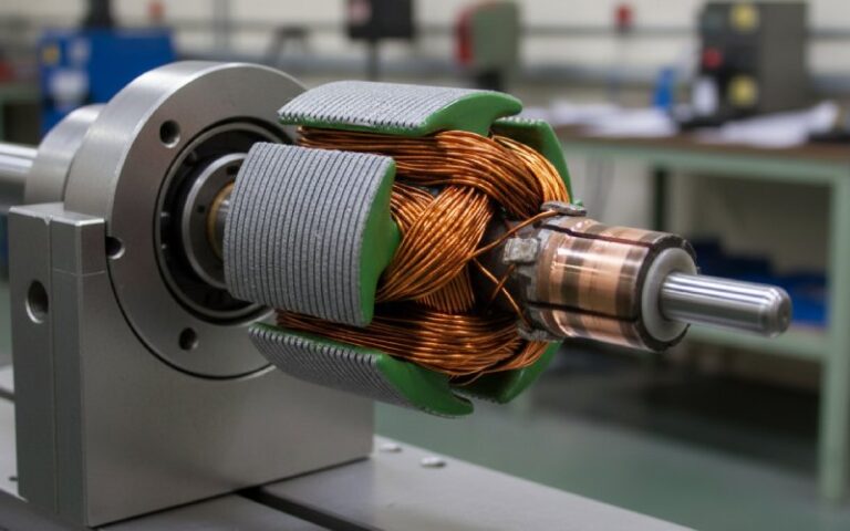
You already know Fleming’s left hand rule, so we’ll skip the textbook diagram and go straight to what the copper feels.
2.1 A single conductor’s view
Take one physical armature conductor:
- For part of a revolution it’s connected to the “+” brush via some commutator segment set.
- Half a turn later, it’s now under the opposite pole and connected to what used to be “–” from its viewpoint, because the commutator swapped which segment meets which brush.
From a fixed stator reference, current through that specific piece of copper reverses direction every half electrical revolution.
So saying “the armature current is AC” is not completely wrong. It does change direction in each coil as the rotor turns. Several machine-theory notes describe DC machines as having AC voltages and currents internally, rectified to DC at the terminals by commutation.
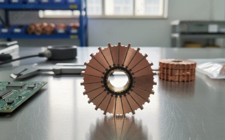
2.2 A coil’s view: commutator as mechanical rectifier and inverter
Now follow a coil rather than one conductor:
- When the EMF in that coil would change sign, the commutator has already swapped its connections to the brushes.
- So the coil “hands over” its ends to the opposite brush pair just as it crosses the neutral plane.
Depending on which side you choose as your reference:
- Generator story: internal AC → mechanical rectifier → external DC.(Ariat Tech)
- Motor story: external DC → mechanical inverter → internal AC-ish currents.
Both stories describe the same copper and the same commutator bars. You’re just looking from opposite ends of the power flow.
2.3 Torque doesn’t care about your naming
Torque only cares about current direction relative to the field, not about your sign convention on the conductors.
The commutator is timed so that, although current in individual conductors flips when they pass the neutral zone, their force direction stays consistent in space. That’s why standard references describe the commutator as keeping armature torque unidirectional.
So:
- Electromagnetically: armature coils operate at some electrical frequency and see alternating induced voltages.
- Mechanically: shaft torque stays in one direction and looks DC-ish.
- At the terminals: you measure DC with ripple.
That’s the whole “internal AC” argument in three lines.
3. So… is a DC motor secretly an AC machine?
Depends which rulebook you use.
Rulebook 1 – Classified by terminal supply
Simple industry rule:
- DC motor: runs from DC supply, no line-frequency stator field.
- AC motor: runs from an AC supply (induction, synchronous, universal, etc.).
Under this rule, brushed DC motors are DC machines, full stop, whatever happens between the bars.
Rulebook 2 – Classified by current in the electromagnets
Some authors classify motors by the nature of the current in the active windings:
- If current in the electromagnets alternates around zero, they call it AC behaviour.
- If it swings between zero and one direction (even if it’s pulsed), they call it DC behaviour.
Using that angle:
- A brushed DC motor: individual conductors see current reversal; fields and torque stay “one-way”. Messy to label.
- A BLDC motor: fed by a DC bus but the stator windings see a clear AC-like phase pattern. Many people still call it a DC motor because of the DC bus.
So:
From the grid’s point of view your brushed motor is DC. From the conductor’s point of view it’s living in an AC world.
That’s why technical blogs talk both about “commutator converting internal AC to DC at the terminals” and “commutator converting external DC to internal AC”.
For catalog labels and purchasing specs, rulebook 1 wins. For electromagnetic design, thermal calculations and commutator design, rulebook 2 quietly shows up.
4. Internal electrical frequency: not just trivia
If there’s “internal AC”, there must be an internal frequency. There is.
Standard relation (same as alternators):
f=P⋅N/120
- (f) = armature EMF frequency (Hz)
- (P) = number of poles
- (N) = speed in rpm
Machine designers pick the pole count so this armature frequency typically sits between 25 and 50 Hz to control core losses.
That’s your AC hiding in a “DC” machine.
Quick internal-frequency cheat sheet
| Motor example | Rated speed (rpm) | Poles (P) | Internal armature frequency (f = P·N/120) | What this hints at |
|---|---|---|---|---|
| Compact 2-pole 3000 rpm DC motor | 3000 | 2 | 50 Hz | Armature core behaves like 50 Hz transformer |
| 4-pole 1500 rpm industrial DC motor | 1500 | 4 | 50 Hz | Typical design choice to limit core losses |
| 6-pole 1000 rpm hoist DC motor | 1000 | 6 | 50 Hz | More poles to keep frequency and losses sane |
| High-speed 2-pole 6000 rpm DC motor | 6000 | 2 | 100 Hz | Higher hysteresis / eddy demand on core & bars |
| 4-pole 750 rpm large-frame DC motor | 750 | 4 | 25 Hz | Lower frequency, bulkier iron, cooler core |
Those numbers are not just for exam prep. They drive decisions on:
- lamination material and thickness,
- bar material and cross-section,
- brush grade and commutation performance,
- EMI noise profile and filtering.
If you’re specifying commutators, it’s worth knowing roughly which row you live in.
5. Why internal AC matters to commutator and brush sourcing
If your business touches commutators, DC motors, or both, the “internal AC” story becomes less philosophical and more contractual.
5.1 Current density is not purely DC
Because each segment is switching current at frequency (f):
- There is a local AC component at the contact interface between brush and commutator bar.
- Contact resistance and film behaviour respond to that switching rate, not just the average DC load.
That affects:
- permissible current per bar,
- brush grade (graphite vs metal-graphite mixes),
- risk of grooving, threading and high brush wear.
5.2 Core & bar heating are frequency-dependent
Armature teeth and core see:
- hysteresis and eddy losses roughly scaling with frequency and (B) level,
- additional localized heating near the commutator because of time-varying current distribution.
So for purchasing:
- a “same current, lower speed” motor may run cooler than a “same current, higher speed” version, even if the copper loss is identical,
- commutator bar material and size that work at 25 Hz internal frequency may be marginal at 100 Hz with aggressive PWM drives on top.
5.3 PWM drives stack another frequency on top
Most modern DC drives use PWM:
- The armature now sees the internal frequency from rotation plus a switching component from the drive.
- That complicates commutation, arcing behaviour and EMI.
If your supplier treats the motor as “pure DC” when picking bar insulation and brush grade, you can get surprises: chatter at certain speeds, radio noise, premature brush wear.
Clear specs around:
- drive type and switching frequency,
- speed range,
- typical duty cycles,
help the commutator supplier design for reality instead of for the old textbook block diagram.
6. Practical checklist for spec’ing commutators and DC motors
When you’re preparing a RFQ or reviewing a motor+commutator proposal, you can quietly apply the “internal AC” thinking with a few simple checks:
- State rated speed and pole count
- Let the supplier compute internal frequency explicitly.
- If they’re surprised by the question, that tells you something.
- Ask for allowable current per bar and per brush at speed
- Not just total armature current.
- You’re checking they’ve considered commutation zone heating, not just copper cross-section.
- Confirm lamination spec vs internal frequency
- Core material grade and lamination thickness should match 25–100 Hz armature EMF range.
- Clarify drive type
- Linear DC, thyristor, or high-frequency PWM?
- Ask for test data with a drive similar to your actual one.
- Request commutation and sparking limits
- Spark quality class (if you use IEC/EN levels).
- Brush life expectations at the worst-case internal frequency (highest speed, highest load).
- Note environment
- Dusty, explosive, or clean environment? Commutator-based machines always bring some arcing and carbon dust.
- Plan maintenance
- Include brush inspection and commutator resurfacing windows in the TCO calculation, especially for larger DC machines.
You don’t need a thirty-page theory appendix in the tender. Just a few well-placed questions that show you know there’s AC hiding inside the “DC” box.
7. FAQ: DC motors and internal AC current
Q1. So, do DC motors actually run on internal AC current?
Short version: yes, in the armature coils you have AC-like induced voltages and current reversals as the rotor turns.
Those voltages are then mechanically rectified by the commutator to give near-DC at the brushes. Many sources describe DC machines exactly this way: internal AC, external DC via commutation.
Whether you choose to call that “running on AC internally” is mostly a matter of naming.
Q2. Is the commutator a rectifier or an inverter?
Both, depending on power flow:
Generator mode: it behaves like a mechanical rectifier, converting armature AC EMF to DC output.
Motor mode: it acts like a mechanical inverter, taking DC from the brushes and distributing it as time-varying currents in the rotating coils.
Same hardware, just opposite energy direction.
Q3. How do I estimate the internal AC frequency in a DC motor?
Use:
f=P⋅N/120
Where (P) is pole count, (N) is speed in rpm. For a 4-pole motor at 1500 rpm, internal armature frequency is 50 Hz.
Designers try to keep this within a range (commonly 25–50 Hz) to control core losses.
Q4. Does knowing about internal AC change how I specify the power supply?
Not really. For the supply, it’s still a DC machine:
You still size the DC drive for voltage, current, and duty.
You still follow the motor’s DC ratings on the nameplate.
Where internal AC matters is:
commutator and brush design,
insulation and core loss evaluation,
EMC and noise mitigation.
Q5. Are BLDC motors “more AC” than brushed DC motors?
BLDC motors:
use an electronic inverter to create a three-phase (or multi-phase) current pattern in the stator from a DC bus,
have rotor magnets following a rotating stator field like a synchronous AC motor.
So yes, in terms of field behaviour they look even closer to classical AC machines. The word “DC” in BLDC mainly refers to the input bus, not to the internal current waveforms.
Q6. If I’m just buying commutators, what’s the one thing to ask?
Ask your supplier:
“What internal armature frequency and drive topology did you design this commutator for?”
If they answer with speed, poles, and drive type — not just “it’s a DC motor, so DC” — you know they’re modelling the same reality your motor will live in.