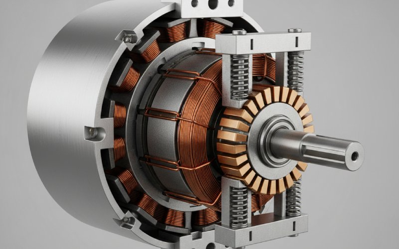
DC Motor Parts: Stator, Rotor, Commutator, Brushes
If a brushed DC motor behaves badly, the root cause almost always lives in one of four places: stator, rotor, commutator, or brushes. These four pieces decide torque ripple, noise, lifetime, and maintenance cost long before anyone argues about drive firmware. You already know what each part is; the interesting work is in how you specify, combine, and abuse them.
Table of Contents
The four parts as a system, not a parts list
Most articles stop at “the stator is stationary, the rotor turns, the commutator and brushes reverse current.” That is technically fine and practically shallow. The real game is in the interactions.
Stator flux sets how hard the rotor copper has to work for each newton-meter. Rotor inductance and slot layout define how long you have to reverse current during commutation. The commutator geometry gives you that time window, or steals it. The brush grade and pressure decide whether the whole system burns that window in heat and arcs. When you see a motor that runs cool, quiet, and boringly reliable, what you are really seeing is those four compromises lining up in a narrow zone of sanity.
Good design is not chasing perfection for each part. It is accepting that when you push one, at least one of the others will complain, and making sure the complaints are minor.
Stator: giving the rotor a fair magnetic job
You already know the stator builds the main field, permanent magnet or wound. Typical references stop there and move on. The more useful question is: how does your stator choice make commutation easy or miserable later?
A high flux density stator lets you shrink the rotor copper for the same torque, but it also pushes you toward higher armature reaction and sharper inductive transients. That shows up at the commutator as sparking. Modern motor work leans heavily on FEA to massage tooth shape, slot opening, and magnet arc so that torque ripple and acoustic noise stay under control and losses stay realistic. If your stator is “efficient” but leaves the rotor facing a very peaky field distribution, you have just moved the problem downstream.
The air gap is the quiet villain. Too large and you waste ampere-turns on magnetizing current. Too small and manufacturing tolerances become a daily argument with the factory: any eccentricity pushes the rotor toward one side, changing local flux and increasing electromagnetic pull. That extra pull couples straight into bearing load and brush vibration. Nobody will trace that vibration back to the original gap decision, but it often starts there.
Lamination thickness, material, and stacking factor look like “core loss” topics only, especially when you read basic tutorials. In practice they also determine how hot the stator frame runs and how much temperature headroom you leave for the brushes. A stator that runs hot forces brush grades with better high-temperature behavior and sometimes poorer commutation, or shorter life. You did not change the brush; you boxed it in.
Rotor: copper, slots, and the amount of time you buy for commutation
Rotor discussion in many guides ends at “laminated core with slots and windings.” For design and troubleshooting, that is the start, not the end.
Slot count and layout are really about how finely you can slice torque and commutation time. More slots give smoother torque and lower ripple, but they also increase manufacturing complexity and can raise leakage inductance. Inductance matters because, during commutation, current has to change direction through those coils in a very short time. High inductance means slow current change and larger reactance voltage, which in turn pressures the commutator and brushes with higher sparking tendency.
The number of commutator segments is tied to the number of armature coils, usually on a one-to-one basis in conventional DC machine design. When you start playing with coil groups, multiplex windings, or fractional slot layouts to save copper or simplify winding, you are quietly editing the commutation process. The moment you share segments between coils in unconventional ways, coil switching no longer happens in neat, symmetric steps. That may still be acceptable, but you need to know you spent commutation headroom to save copper or bar count.
Thermally, the rotor has the worst job in the machine. Losses in the copper and iron have to find their way through rotating structures into air or a fan. If you run the copper near its limit and shrink the rotor for cost or inertia, you often end up with stable electrical behavior and marginal brush life, because the commutator runs hotter than the data sheet assumed. Heat does not care that you technically met current density limits on paper.
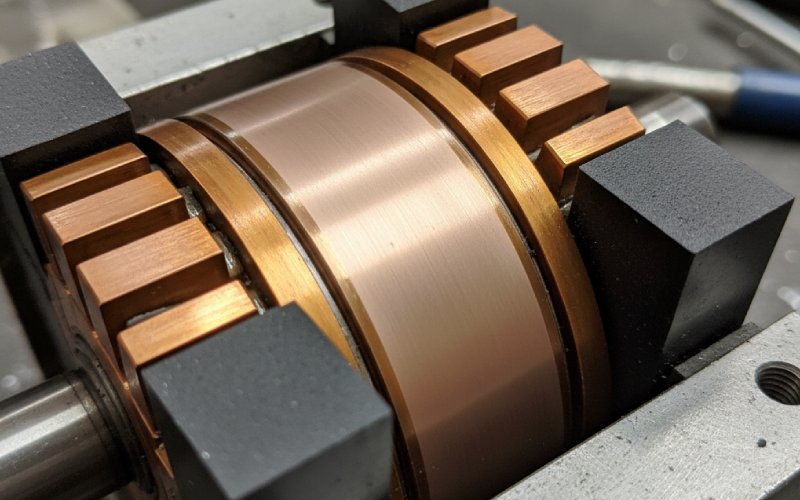
Commutator: copper geometry as a timing device
Most introductions describe the commutator as “a set of copper segments that reverse current via the brushes.” Accurate, again, but the design details are where motors either behave or misbehave.
Diameter is not arbitrary. A widely used guideline is to keep the commutator diameter between about sixty and eighty percent of the armature diameter, with small machines sometimes going a bit higher. Diameter and speed together give you commutator peripheral velocity. Traditional design notes suggest staying near or below roughly fifteen metres per second where possible, with thirty metres per second seen in practice but known to shrink commutation time and make sparking more likely.
That surface speed ties directly into brush wear. Manufacturer data shows brush wear rising from roughly three millimetres per thousand hours below twenty metres per second to around seven millimetres per thousand hours as you approach forty metres per second. A design that looks fine at nominal speed can quietly become a brush grinder the moment someone increases rated speed for marketing reasons.
Segment pitch sounds boring until you try to repair a motor that was pushed too far. Design notes commonly suggest commutator bar thickness not much below about four millimetres, with fractional-kilowatt machines sometimes dropping to about two and a half millimetres. Thin segments save axial length and material, but they also raise resistance, reduce heat capacity, and make mica undercutting and resurfacing harder. You win a shorter motor and pay with more sensitive commutation and trickier maintenance.
Roundness and surface finish are the hidden levers. Industrial practice expects commutators running around five thousand feet per minute peripheral speed to stay within about 0.001 inch concentricity, tightened to about 0.0005 inch at higher speeds. Surface roughness targets in the region of Ra 0.8–1.2 micrometres are often cited as a sweet spot for good brush seating and film behaviour. Too smooth and brushes skate, film breaks, and you get streaking; too rough and you physically chew the carbon.
So the commutator is not just a connector. It is a mechanical timing and interface component with tolerances that sit right at the edge of what many production lines enjoy holding.
Brushes: one small part carrying all the current
If the commutator is the timing wheel, brushes are the only legal way onto the wheel. They have to carry full armature current, tolerate arcs, maintain a film, and not self-destruct too quickly. That is a long job description for a block of carbon.
Technical guides for carbon brushes usually quote current density ranges around eight to sixteen amperes per square centimetre, with many grades optimised near ten to thirteen amperes per square centimetre. That is not a “pick any value” range. Operating far below it can lead to unstable film formation and erratic contact resistance; running far above it simply turns the brush into a resistor and heater.
Brush pressure is the other big lever and is very easy to get wrong. For stationary machines, values around 180–250 grams per square centimetre, which is roughly eighteen to twenty-five kilopascals, are widely recommended. Heavily vibrated machines, such as traction motors, may need 350–500 grams per square centimetre. If pressure drops below roughly thirty kilopascals in some high-speed applications, studies show arc erosion becoming the dominant wear mechanism. Increase pressure too much and you reduce contact drop, which sounds appealing but actually makes commutation harder because the brush loses some of its “buffer” behaviour.
Brush manufacturers publish large tables of grades, mapping them to voltage, speed, commutation severity, and expected film behaviour.When you have a problem machine and simply ask for “a harder grade” or “a higher current grade,” you are often stepping outside those maps without saying so. The brush then tries to stabilise a film on a commutator that may be too fast, too hot, or too rough for that choice. The result gets labelled “brush issue” even though the real cause is an earlier design compromise that silently changed the operating window.
Split brushes and special constructions exist exactly because the basic compromise is tight. Dividing a brush into two or three sections increases the number of contact points and the transverse resistance, which can improve commutation at high current and speed. These tricks are a hint: the basic, solid block is already working at the edge of multiple constraints.
How the four parts lock together: a quick interaction map
It helps to see the interactions in one place. The numbers here are typical ranges drawn from common design and maintenance references rather than strict rules.
| Part | Key design knob | Typical range or target | What usually goes wrong when you push it too far |
|---|---|---|---|
| Stator | Flux density in teeth and yoke | Chosen to avoid saturation while keeping copper reasonable | Rotor copper overheats, torque ripple and noise increase, commutation margin shrinks |
| Stator | Air-gap size and uniformity | Small but manufacturable; eccentricity kept tight | Unbalanced magnetic pull, bearing stress, brush vibration |
| Rotor | Slot count and winding layout | Enough slots for smooth torque without excessive inductance | High inductance hurting commutation, or visible torque ripple |
| Rotor | Thermal path from copper to air | Adequate cross-section and ventilation for loss levels | Commutator runs hot, brush grades forced into narrower choices |
| Commutator | Diameter ratio to armature | About 0.6–0.8 of armature diameter | Either too small (high current density, less surface) or too large (space and inertia) |
| Commutator | Peripheral speed | Preferably ≤15 m/s, with 20–30 m/s as upper area used with care | Sparking, higher brush wear, stricter concentricity needs |
| Commutator | Segment thickness | Roughly ≥4 mm, down to about 2.5 mm for small machines | Fragile segments, difficult maintenance, poor heat dissipation |
| Brushes | Specific current density | Often in the 8–16 A/cm² envelope, many grades near 10–13 A/cm² | Overheating, rapid wear, unstable film, or erratic contact resistance |
| Brushes | Specific pressure on commutator | Around 18–25 kPa for stationary machines, higher for vibration | Too low: arcing and erosion; too high: excessive wear and weaker commutation buffer |
| Brushes | Grade and film behaviour | Selected from manufacturer maps for speed and voltage range | Streaking, threading, grooving, or noisy commutation |
You can read the table from any direction. Start at brushes and you see that most “brush problems” originate in commutator speed, temperature, or stator-rotor choices. Start at stator flux and you can predict that aggressive flux levels will require a calmer commutator and more tolerant brush grades to stay stable.
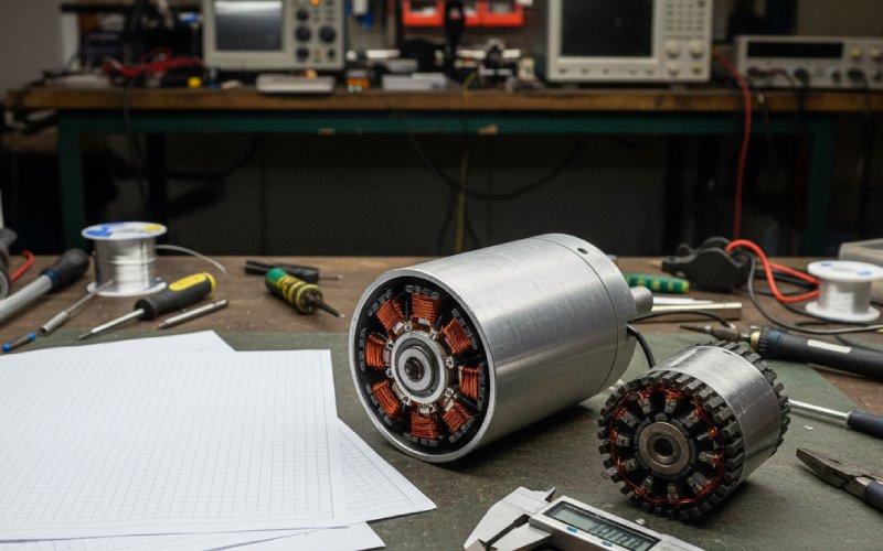
Reading a troubled DC motor through these four parts
Maintenance guides often emphasise the commutator as the single most important indicator of machine health. That is not superstition; it is a practical shortcut. The commutator physically sits between rotor currents and brush behaviour, so it collects evidence from both.
A smooth, uniform film, usually somewhere between light and dark brown depending on grade and environment, is boring and good. Technical brush guides treat this as a normal state. If instead you see heavy grooving, copper drag, or slotting aligned with brush tracks, maintenance articles on DC motors will point you straight back to contamination, wrong grade, or incorrect current density.
Uneven film tone around the circumference often means the air gap is not uniform or the magnetic field is distorted. That takes you back to stator and rotor geometry, even though the symptom is “on the commutator.” Threading patterns and localized burning near neutral planes hint that commutation time is too short for the inductance and current involved, which returns you to rotor layout and commutator diameter or speed.
Brush wear rates that differ from manufacturer expectations at a known peripheral speed can usually be traced through three questions. First, is the speed actually what the nameplate claims, or has the drive pushed it? Second, has brush pressure drifted over time due to tired springs? Third, has the environment changed – chemical vapours, humidity, airborne particles – that affect film formation? Maintenance documents call these out explicitly because they show up again and again.
By forcing yourself to route every symptom through “which of the four parts is shouting, and which one caused it,” you avoid random fixes. Replacing brushes on a machine with poor concentricity or excessive commutator speed will buy only temporary relief.
Using this in design reviews
Most design reviews for DC motors spend a lot of time on performance plots, drive compatibility, and regulatory items. There is usually less time on whether the machine can live with itself mechanically and electrically over long operating hours. A simple way to rebalance is to structure review questions around these four parts.
Start with the stator and ask how conservative the flux and air gap decisions are. If the design leans hard on high flux density to meet torque within a given frame, make a mental note that the commutator and brushes will have to work in a sharper magnetic environment. Then look at the rotor data: slot count, winding style, and estimated inductances. That will tell you how abrupt current changes will be during commutation.
Next, examine the commutator drawing as though it were its own product. Check the diameter ratio, segment thickness, and calculated peripheral speed at all operating points, including any overspeed or field-weakening modes. If the numbers edge into “works, but only with perfect maintenance,” that is exactly the sort of risk that becomes expensive later.
Finally, map brush grade, current density, and pressure back to manufacturer recommendations instead of treating them as loose suggestions. If a grade is chosen at the very edge of its speed or current envelope to make the electrical design look neat, say so explicitly. It is much easier to adjust copper or commutator geometry in CAD than to rebuild a fleet of motors in the field.
Closing thoughts
The official descriptions of stator, rotor, commutator, and brushes give you nouns. Real motors care about verbs: saturate, heat, erode, arc, cool, wear. Those verbs are controlled by a handful of geometries, material grades, and operating numbers scattered across these four parts.
Once you already understand how a DC motor works, the useful step is to treat these parts as a tightly coupled constraint problem instead of a block diagram. When you choose stator flux, you are also choosing brush grade options. When you raise speed, you are rewriting commutator surface limits and brush wear. When you simplify rotor winding, you are editing commutation time.
You can accept those links or ignore them, but the motor will follow them either way.