Commutators in Railway Traction and Legacy DC Systems
Commutators decided how early electric trains behaved, and they still decide whether a surprising number of modern locomotives make it back to the depot or fail on the line. AC drives might own the future, but for legacy DC fleets the commutator–brush system is still where reliability is quietly won or lost.
Table of Contents
Why commutators still matter in an “all-AC” era
Most new rolling stock now leaves the factory with three-phase AC motors and IGBT converters. DC traction motors with commutators have been steadily displaced because AC machines are simpler mechanically and cheaper to maintain over life.(ScienceDirect)
Yet heavy-haul locomotives, older EMUs, metros from the 1970s–1990s, and a sizeable chunk of mining and industrial rail still depend on big DC series motors. In many of those fleets, bogies, gearboxes and motor frames can run for decades longer, but commutators and brushes define the practical retirement date. Spare motors and commutator blanks are not always the limiting factor; specialized knowledge is.
There is another reason they matter. A lot of the intuition behind modern vector-controlled AC drives comes from the classical DC commutator machine. The two-axis dq description used in field-oriented control is essentially a mathematical echo of what the commutator and brushes do mechanically. Losing commutator know-how means losing some of that original physical feel for torque production and current control.
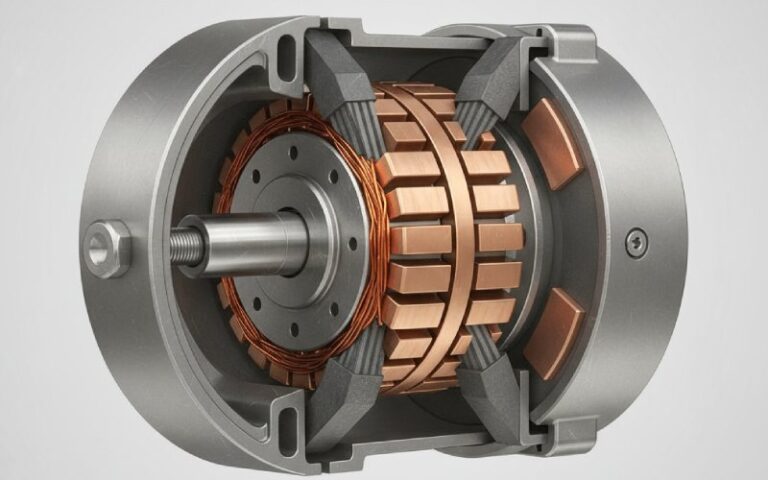
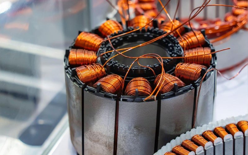
The commutator as a mechanical converter, not just a copper drum
By now you know the textbook line: segmented copper cylinder, carbon brushes, current reversal. What tends to get glossed over is that the commutator is a mechanical frequency converter embedded in a violently vibrating environment. Shantarenko and co-authors describe the commutator–brush assembly explicitly as a mechanical converter of electrical frequency, and then proceed to treat its sparking behavior statistically, which is closer to reality in traction service than any neat phasor diagram.
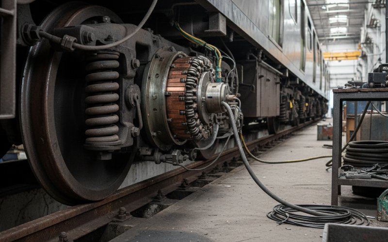
In railway traction the armature current is rarely “rated and steady”. Starting a heavy freight train or pushing a metro set off the platform loads the DC series motor well beyond nameplate for short periods. The commutator has to commute thousands of amps under armature reaction, with the interpoles doing their best to clean up the induced voltages. When the wheelset slips, or a driver yanks the power handle, or the traction control system hunts for adhesion, all of that ends up as stress in a few millimetres of copper and film.
So the commutator is not just transferring current. It is trying to maintain an illusion of smooth torque while the system keeps asking it to behave like a modern current-regulated inverter. That mismatch is exactly where many of the ugly failure modes start.
Railway duty cycles and what they do to commutation
Urban DC metros sit at the hard end of the spectrum. Short station spacing, aggressive acceleration and heavy braking make the traction motors live in a world of sharp current changes, repeated several times per kilometre. The commutator never truly settles into a clean thermal steady state. Film formation, brush wear and copper temperature all run on different clocks, so you can have an apparently fine commutator that is actually skating along the edge of thermal softening during peak hour.
Heavy-haul locomotives stress the system differently. Continuous high load on long grades keeps armature current near maximum for long stretches, which raises copper temperature but with fewer fast transients. Under these conditions, patterns like copper drag and slot bar burning become more likely, particularly if brush grade or spring force has been optimised too aggressively for low wear.
Then there is regenerative braking on DC systems. On older EMUs, regen was sometimes retrofitted onto motors that were designed with pure motoring in mind. The current reverses, the magnetic conditions in the commutation zone shift, and what was a stable setup in motoring can become marginal in regen, especially at low speed. You end up with “it only sparks badly downhill” reports from drivers that are easy to shrug off but often point to real commutation margin problems.
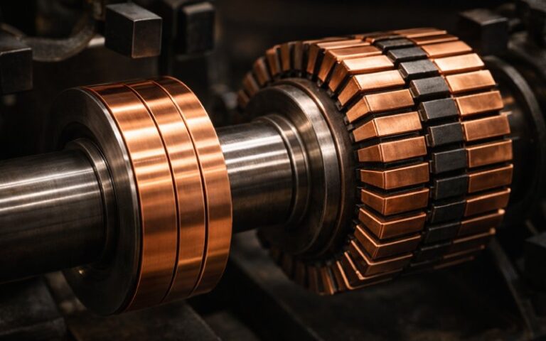
What actually fails in traction commutators
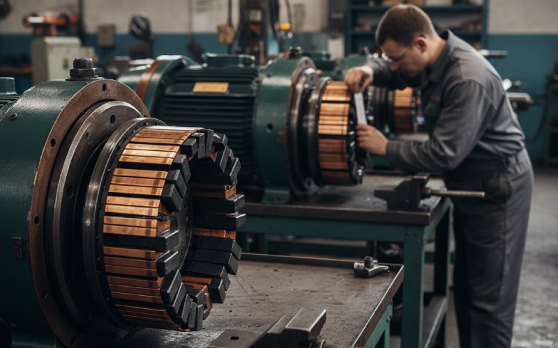
The obvious answer is “they wear out”. But that is not really the story. The commutator–brush zone is a coupled electromechanical system, and most serious failures start with a small imbalance there. Carbon brush handbooks are blunt about it: current density, brush grade, contact surface condition and holder geometry all interact, and none of those parameters can drift very far without visible consequences at the copper interface.
Maintenance guides for industrial and traction machines list a familiar set of defects: grooving, copper drag, bar edge burning, slot bar burning, high mica, loose bars. The trick in a railway context is to connect those surface patterns back to the duty cycle, cooling hardware and control strategy of the vehicle, instead of treating each commutator as an isolated workshop job. A metro car that spends half its life in tunnels with marginal dust filtration will age its brushes and film in a different way from a mining locomotive that lives in abrasive dust and wild temperature swings.
The reliability literature for traction motors increasingly treats commutator behavior statistically, using metrics like arc pulse duration distributions to assess sparking level and predict failure risk. That kind of thinking is still rare in depots, where “visual inspection and the technician’s ear” remain the main tools.
A field view: symptoms, mechanisms, and what they are really telling you
Instead of a shopping list of faults, it helps to keep a compact mapping between what you see, what is likely happening in the commutation zone, and what is actually at stake for the fleet. The table is deliberately simplified, but it aligns fairly well with the major guides used in industry.
| Field symptom on DC traction commutator | Likely underlying mechanism in traction service | First questions to ask in the depot | Practical risk if ignored |
|---|---|---|---|
| Uniform light brown film, smooth surface, low brush wear | Film and current density in balance; interpoles correctly set; vibration under control | Has anything changed in brush grade, filtration or duty cycle since last overhaul? | Low; mostly a reference case for “normal” in your own fleet |
| Heavy but even dark film, brushes running cool | High humidity or polluted air aiding film build-up; possible slight under-loading in some parts of the cycle | Did timetable changes lengthen coasting or low-load running, or did control software reduce current peaks? | Moderate; can hide early copper drag if temperatures creep up later |
| Pronounced grooving in brush direction | Abrasive brush grade or contaminated air; localized arcing machining the surface | Has brush grade migrated from a softer to a harder family; have filters clogged; is there visible dust ingress pathways near the motors? | High; grooves concentrate current, raise local temperature and shorten commutator life dramatically |
| Copper dragged over slots, smeared appearance | Copper softening due to high temperature and mechanical vibration; sometimes overly abrasive or unstable brush grade | Are commutator temperatures being monitored; has continuous load increased; have vibration levels changed after wheel reprofiling or bogie work? | High; once drag starts it tends to self-accelerate and can ruin a commutator between overhauls |
| Bar edge burning on every second or third bar | Poor commutation timing, incorrect neutral setting, or weakened interpoles; sometimes mismatched brush voltage drop | Did someone move brush rigging; have field or interpole currents been modified in control upgrades; is the chosen brush grade still in spec for this motor type? | Very high; often a precursor to insulation damage and forced motor replacement |
| Random dark bars, intermittent sparking reports from drivers | Loose bars, uneven contact pressure, or local insulation issues | When was the last bar-to-bar test; has the motor suffered a past flashover or mechanical impact; are brush holders clean and square? | Very high; loose bars in traction motors can escalate to catastrophic failure under load or during regen |
| Localized flat spots with no obvious discoloration | Previous skim with insufficient deburring, or uneven wear after misaligned brushes | Was commutator skimmed on-vehicle; were brushes run in properly afterwards; are holders aligned to manufacturer data? | Medium; may start as a comfort issue (noise, minor sparking) but can grow into more serious defects |
This way of thinking is boringly pragmatic. But it helps keep the conversation in the depot focused on system causes instead of just surface machining and brush replacement.
Brushgear decisions: where most of the subtlety lives
Suppliers now offer a bewildering range of carbon grades for traction, often with rail-specific formulations that trade wear against commutation stability and acceptable film formation. Application guides for GE and similar traction motors show grades such as T900, T959 and T593 being approved for particular motor families, often in multi-wafer brush constructions to improve contact stability in high-vibration environments.
Those multi-wafer designs and hard grades are not just marketing. They exist to deal with bogie vibration, commutator ovality, and the frequent low-speed, high-torque operation that comes with moving very heavy trains. But applying a “railway grade” blindly can backfire. An overly hard grade on a fleet with marginal cooling can drive commutator temperature up and trigger copper drag. A very soft grade chosen to protect the commutator on an old fleet can create dust problems and unstable film, especially in tunnels with weak filtration.
Brush voltage drop is another quiet variable. The commutation window in a traction DC motor is narrow. If brush voltage drop is lower than what the interpoles and neutral plane were designed around, you can drift into bar edge burning even though the machine looks fine on a no-load run. That is exactly why many wear guides tie edge burning back not only to magnetic settings but also to brush material.
Nineteenth-century hardware under modern power electronics
Some of the hardest problems appear when legacy DC traction motors are driven from more aggressive power electronics than they were designed for. Early systems used series–parallel switching and resistor banks or simple chopper controls. As converters improved, OEMs and operators began feeding the same motors from faster, higher-frequency choppers or rectifiers, with tighter current regulators. The external torque response improved. The commutator saw steeper current ramps and more frequent transitions.
On mixed networks, DC locomotives may be fed from substations that now also support modern MVDC applications, where the traction supply can serve as a backbone for urban DC loads or microgrids. From the commutator’s point of view, this can mean slightly different ripple content, different fault clearing behavior and altered regeneration patterns. None of that shows up in the original motor drawings. It shows up as odd wear patterns a few years after the power system upgrade.
As AC–DC–AC conversion became standard for new locomotives, DC traction motors started to disappear from mainline specs, but the remaining fleets often ended up in harsher service: leftover duties, work trains, low-priority freight. Those operating patterns can be surprisingly abusive, with frequent starts, low speeds and poor track quality, and they leave their own signatures on commutator condition.
Diagnostics that actually change decisions
Modern research on commutator behavior in traction focuses on quantifying sparking by measuring the duration and distribution of arc pulses at the brush–commutator interface. The idea is to move beyond subjective “spark grades” toward probabilistic indicators of commutation quality. In practice this can link into existing condition-monitoring systems, combining current sensor data, vibration and temperature with arc statistics.
For many fleets, though, the realistic path is a step or two more modest. What tends to work is consistent visual documentation of commutator condition at each scheduled inspection, coupled with simple measurements like bar-to-bar resistance, total indicated run-out and brush spring force. Add train-borne data such as traction current profiles and slip–slide logs, and you already have enough to correlate aggressive driving patterns or timetable changes with accelerated commutator wear. Over a few years, this becomes a fleet-specific commutation “map” that beats any generic handbook.
Extending life versus accepting replacement
At some point a commutator has been skimmed too often, the slots have been undercut too many times, and the risk of insulation failure makes continued refurbishment false economy. The difficulty is that the financial break-even point moves when OEM support dries up or the cost of a new AC drive retrofit is high.
Carbon-brush suppliers and commutator wear guides tend to promote machining, rewinding and re-insulating as a routine cycle. That can work for industrial drives. For traction, every additional removal of the motor, every lift of the vehicle, every time you disturb heavy cables and cooling ducts, there is extra system risk. The decision is not only about the copper cylinder. It is about downtime, fleet availability, and the practical skills available in your workshops.
One useful tactic is to classify motors into “full life left”, “salvage by refurbishment” and “run-to-replacement” at each major overhaul, based on commutator condition, insulation tests and historical data. Motors in the last group can be paired with vehicles that are themselves near end of life. That way you avoid spending commutator money on cars that will be scrapped soon anyway.
Where this leaves us
AC traction, permanent-magnet motors and solid-state converters get the engineering attention, and rightly so. But the commutator–brush assemblies under a lot of ageing trains are still determining how much real capacity operators can squeeze out of their networks. A single mis-chosen brush grade or an unnoticed shift in duty cycle can quietly consume what life is left in a fleet’s traction motors.
Treating commutators in railway traction as a living, coupled system rather than as legacy “copperware” makes the work more interesting and more honest. It connects depot observations with control software decisions and with system-level upgrades to power supplies. Once you start joining those dots, commutators stop looking like relics and start looking like what they have always been in DC traction: compact, slightly awkward mechanical converters that still carry a surprising amount of the system’s fate on their shoulders.