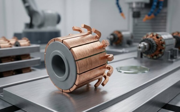
Commutators in Airsoft and Gaming Motors: Performance and Reliability
If the commutator is right, the motor just works and keeps working. If it isn’t, every fancy magnet, winding pattern, and MOSFET you bolt around it is just compensating for a weak link. This is the quiet piece of copper that sets the ceiling on trigger response, ROF, force feedback feel, and long-term reliability. Everything else is downstream.
Table of Contents
You already know what a commutator is. So what actually matters?
You know the drawings and the equations. Copper bars, brushes, switching, torque. What the datasheets rarely say is how brutally application-specific commutator behavior is. The same basic design lives in an AEG motor pulling 50+ amps on a hard semi-auto spam, and in a tiny rumble motor in a gamepad that barely warms up over its lifetime. Same physics, completely different failure story.
Public guides on brushed motors focus on generic maintenance: clean the commutator, keep the brushes healthy, avoid obvious abuse. Useful, but shallow. Once you push AEG builds into 30–40 RPS territory or ask a compact force-feedback motor to stay linear over hours of racing, the boring details of commutator geometry, timing, surface condition, and film become the actual tuning knobs.
So the goal here is simple: treat the commutator as the main design variable, not an afterthought, and tie that directly to how your airsoft or gaming setup performs and survives.
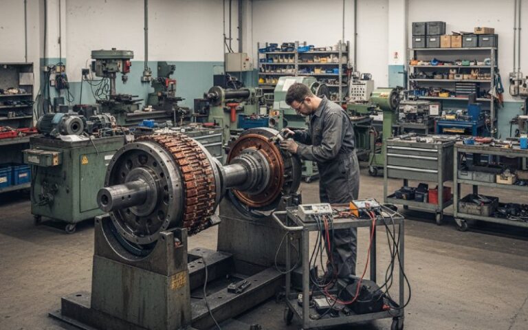
Airsoft AEG motors: bursts, heat, and commutator stress
AEG motors live a rough life. High spring loads, stacked gear ratios, aggressive LiPo packs, and a control style that’s almost designed to torture commutators: short bursts, high dI/dt, then idle. Community data for common 12:1–13:1 builds shows 20–40 RPS with high-torque or high-speed motors, running on 11.1 V and fairly stiff springs. That means serious current pulses and repeated arcs at the brush edge.
In this regime, the commutator is both a performance gate and a fuse. When it is flat, round, with the mica correctly undercut, brushes well seated, films stable, you get sharp trigger response and predictable ROF. When it goes off even a little, the system lies to you. You start blaming shims, MOSFET, or battery sag while the copper is telling the real story.
Typical AEG symptoms line up nicely with commutator condition:
The motor that screams unloaded but falls flat under spring load often has poor brush seating or a rough comm surface. Arcing becomes intense under load and the effective torque constant drops.
The setup that starts hot-smelling and noisy after a few game days usually shows darkened segments, raised mica, or carbon bridging between bars, all of which increase heating and cause mis-commutation.
The “mystery death” motor that lost torque but ohms out fine regularly turns out to have lifted connections between the windings and commutator lugs or overheated adhesive, not burnt windings.
Most guides just say “clean it.” True, but incomplete. The real edge comes from treating the comm as a precision part with its own geometry and life cycle.
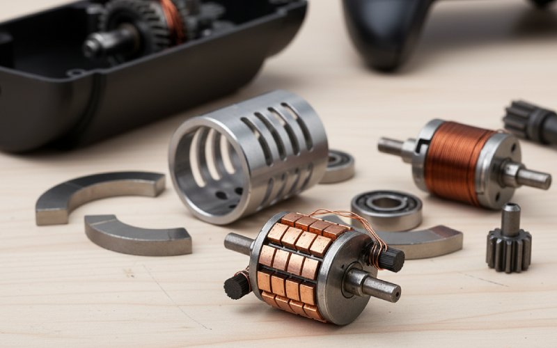
Gaming and haptics motors: not the same abuse, not the same priorities
Gaming hardware has its own classes of brushed motors:
Small eccentric-mass rumble motors in controllers and handheld devices.
Medium brushed DC motors in older or budget racing wheels, pedals, flight sticks, and similar gear.
They don’t see AEG-level current spikes, but they often run for longer continuous periods and at high PWM duty, which changes the commutator game.
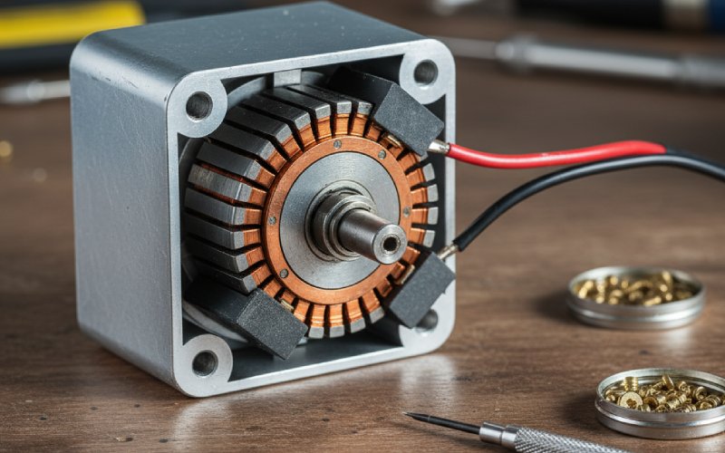
In gamepad-sized motors, the commutator is tiny and spins at very high RPM for its size. Arcing is not just a reliability issue; it’s an EMI and noise issue. Excessive brush sparking in small motors is typically tied to poor brush seating, rough comm surfaces, or carbon dust accumulation between bars. For controller designers, the question is less “will it pull the spring?” and more “will this thing stay quiet electrically and mechanically over thousands of hours.”
In force-feedback wheels and similar gear, some models still use brushed motors for cost and simplicity, even if high-end products are moving to brushless designs. These motors see strong bidirectional torque, frequent rapid reversals, and long sessions. Now the commutator has to deal with:
High average current instead of short bursts.
Repeated transitions between motoring and generating (during braking or centering).
Strong influence from PWM frequency and driver design on how clean the current switching is.
Here, commutator wear tends to show more as glazing and uneven film rather than catastrophic burn marks, at least until something else in the mechanical drive goes wrong and starts feeding vibration back into the motor.
So airsoft cares about peak current, recovery, and thermal abuse. Gaming hardware cares about smoothness, noise, and endurance. The comm is the same type of component, but the trade-offs are not the same.
Timing and brush geometry: speed, torque, and smoke
Once you start pushing performance, commutator timing becomes a very real tuning axis. Slot car and RC documentation is surprisingly relevant here, because those communities have been adjusting timing for decades. The basic idea: rotate the commutator relative to the rotor so the current in each coil switches slightly before the magnetic poles line up, compensating for inductive delay at high speed.
Advanced timing gives you:
Higher top speed at a given voltage and load.
More current draw and more heating, especially at low speed.
A strong preference for one direction; running it backwards for long can cook it.
The same physics applies to AEG and gaming motors. A slightly advanced armature will feel sharper in semi and give higher ROF in full auto for the same gear ratio. It will also run hotter and be more sensitive to poor comm condition. If the commutator is not truly round, or the brushes are not seated, that timing advance turns mild sparking into a light show.
Brush geometry then acts as the other half of this equation. The shape and hardness of the brush tip control how quickly the contact area grows during break-in, how the film forms, and how tolerant the system is of small timing changes. RC and crawler literature often mentions timing ranges around 6–12 degrees and low-voltage break-in until 90% of the brush face is contacting the commutator. The exact values differ for AEG motors, but the principle is identical: faster seating means lower localized heating and cleaner arcs.
In gaming motors, timing is often fixed and conservative, because no one wants a racing wheel that eats motors every few months. But if you are designing your own hardware or replacing motors with “hotter” units, ignoring timing while changing magnet strength or supply voltage is a good way to shift the commutator into a wear regime you did not plan for.
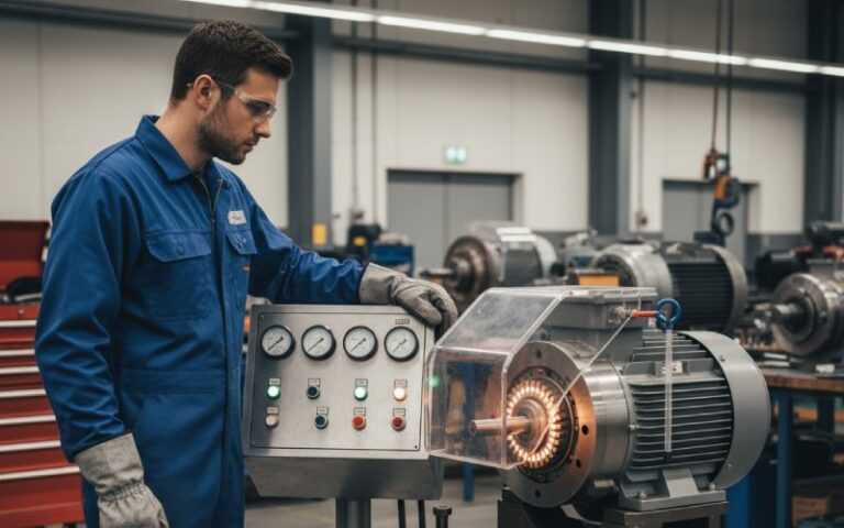
Surface condition and film: clean is good, too clean is slow
Most articles tell you to clean the commutator with alcohol, maybe fine abrasive, and call it a day. That’s the starting point, not the strategy.
A brushed DC motor commutator actually wants a controlled surface film. Technical notes on brushed DC maintenance point out that the right oxide and carbon film lowers contact resistance, stabilizes friction, and reduces metal transfer between brush and commutator. Over-aggressive cleaning that strips this film can increase wear and noise.
For high-stress AEG motors, the practical pattern looks roughly like this:
A new or resurfaced commutator is bright, maybe mirror-polished. During break-in, carbon and copper films form. Voltage drop and sparking usually improve as the film stabilizes.
If the motor sees a lot of arcing from misalignment, over-voltage, or late timing, you get patchy dark bands and pitted copper. Here, cleaning and sometimes a light skim are warranted.
If the comm surface feels rough or scorched, guidelines from industrial and motor-specific sources recommend very fine abrasive (around “0” emery or 600+ grit) applied with the motor spinning, or a true skim cut on a lathe or dedicated truing machine for serious damage.
Gaming motors benefit from similar logic, but with more conservative steps because the commutators are smaller and driver electronics are tuned to a specific friction and noise profile. Often, simply blowing out carbon dust, checking brush length, and wiping the comm with contact cleaner is enough. Heavy resurfacing is a last resort.
The trick is to recognize that the right surface is not “shiny at any cost”; it is “smooth, round, and carrying a stable, thin film.”
Failure patterns you can read at a glance
Once you start looking at commutators as diagnostics, they tell you a lot with no scope and no math.
Uniform light brown ring with very fine, even brush marks usually means a well-seated brush and healthy film. This is often seen in well-run slot and industrial motors and is what you want to see in a mature AEG or gaming motor.
Dark, almost black patches with visible pitting on one side of each segment often mean timing is too advanced for the load or supply voltage, creating strong arcs as the coil current is cut late.
Copper smeared across insulation slots or carbon dust filling them shows that either the slots were never properly undercut or the motor has been arcing and shedding material for a while. In AEG builds, this often appears alongside unexplained current spikes and hot battery leads.
Ridges where the mica insulator stands proud of the copper bars tell you the comm needs the mica undercut and the copper re-finished. Running in this state keeps the brushing riding on the mica edges, reducing real contact area and increasing localized heating.
Blue or straw-colored areas on copper indicate serious overheating. At that point, you should be suspicious of the solder joints under the commutator lugs and of the rotor epoxy, not just the visible copper.
Once you read these patterns, you stop guessing. You open a motor, look at the comm, and know whether the problem is gearing, timing, voltage, or simple neglect.
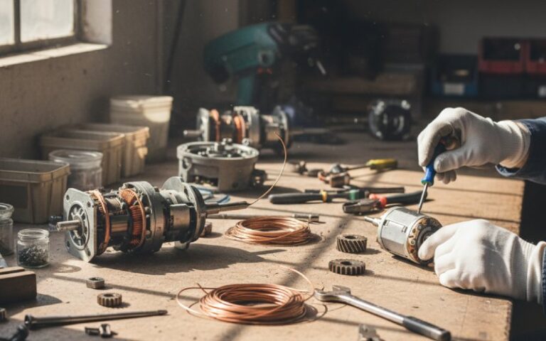
Break-in: not superstition, just controlled damage
Break-in is sometimes treated as folklore in the airsoft and hobby communities. Someone says “run it in water,” someone else says “never do that,” and it becomes a debate. The underlying physics is straightforward: you are wearing the brush face to match the comm curve while trying to limit heat and metal transfer.
RC, slot, and crawler communities often use low-voltage no-load break-in, anywhere around 1–3 V for a few minutes, to let the brush conform without major arcing. Some airsoft techs adapt the same method, occasionally with distilled water baths to carry away debris and limit surface temperatures.
From a commutator perspective, a sensible protocol has a few simple goals:
Keep voltage low enough that current is modest and arcs are small.
Keep run time just long enough to gain high contact coverage, not so long that you chew through brush material.
Clean out the motor after break-in so brush dust does not short the comm slots.
For gaming motors in controllers, there is usually no user break-in step; the manufacturer does it in-house or designs for a safe early-life wear period. But if you are replacing motors in a wheel or custom haptics device, adopting a brief low-voltage break-in before full-power testing makes commutator behavior much more predictable.
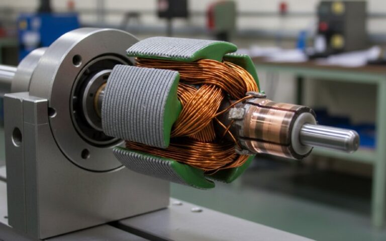
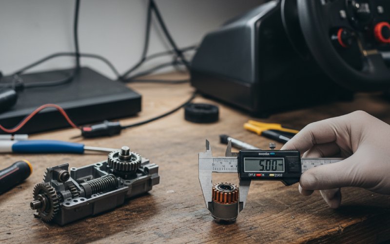
Design choices: materials, diameter, and current paths
If you go one level deeper and think like a motor designer, the commutator has a handful of levers that directly affect performance and reliability:
Copper alloy and bar geometry determine how well the commutator balances conductivity, mechanical strength, and arc erosion. Slot car and industrial discussions point out that commutators must transmit high current while staying mechanically stable at very high RPM; the material is always a compromise. AEG motors running 30–40k RPM with 3-pole armatures have similar needs.
Diameter sets surface speed for a given RPM. Higher surface speed with the same brush and current means more wear and more heat at the brush face. This matters in small gaming motors that spin very fast.
Segment count and slot depth influence how cleanly current can be commutated and how sensitive the system is to carbon bridging. Shallow slots that fill with dust turn into resistive or even conductive paths, especially in dirty environments.
Connection method from winding to comm bar (hook, tang, welded, or soldered) sets the long-term robustness of the joint. Airsoft motors using soft solder may be more vulnerable to desoldering during abuse than welded comms, especially under sustained semi-auto spam.
Driver electronics, especially PWM frequency and current limiting, shape the actual waveform arriving at the commutator. Low PWM frequencies let current fully decay between pulses, which can reduce average heating but make each commutation event sharper. Higher frequencies can smooth torque but demand faster switching from the comm and brushes.
None of this is mysterious. It just means that a “better motor” is often a better commutator design paired with matching electronics, not just stronger magnets and thicker wire.
Quick comparison: commutator priorities by application
The practical differences between airsoft and gaming use cases are easier to see side by side.
| Application | Typical Duty Pattern | Main Commutator Stress | What Usually Fails First | Best Return on Attention |
|---|---|---|---|---|
| AEG airsoft motor (high RPS) | Short, high-current bursts; frequent starts | Intense localized heating and arcing | Brush edges, comm pitting, joints | Proper timing, break-in, slot cleaning, true running |
| AEG airsoft motor (DMR / semi) | Repeated semi-auto, medium current | Hot spots near frequently used angles | Uneven film, partial glazing | Brush seating, watching for dark bands and ridges |
| Gamepad rumble motor | Long low-to-medium load sessions | High RPM, moderate current, EMI noise | Brushes glazing, minor out-of-round | Keeping dust out, choosing quiet drivers and timing |
| FFB wheel / pedal motor | High torque, frequent reversals, long sessions | Bidirectional current, thermal cycling | Commutator film instability, bearings | Conservative timing, stable film, cooling |
This is not a rigid rule set, but it captures why a maintenance trick that makes sense on an AEG might not be smart for a controller, and vice versa.
Reliability mindset: treating the commutator as the primary consumable
If you approach brushed motors assuming “they hardly ever really die; it’s usually cleaning and brushes,” you’re already halfway to a commutator-centric philosophy. Tech discussions across hobbies repeatedly point out that many “dead” motors come back once dust is cleared, commutators cleaned, or brushes replaced. The remaining failures usually trace back to overheating or mechanical abuse, not some mystical aging process.
For airsoft, this means:
You stop treating motors as disposable consumables and instead plan regular comm inspections, especially on high-ROF builds.
You match spring, gear ratio, battery, and timing with comm durability in mind, not just ROF and trigger feel.
You keep notes on current draw and performance over time. A slow creep in current at the same ROF often matches growing comm dirt or slot contamination.
For gaming and haptics devices, it means:
You design protective electronics that limit peak current and avoid comm-destroying transients.
You accept that some comm wear is normal and design the device to make motor replacement easy rather than painful.
You pay attention to the audible “texture” of the motor. Changes in brush noise, even before any major performance loss, tend to mirror changes in comm surface condition.
In the end, commutators are not glamorous. They are small, often hidden, and almost never the headline feature on the box. But they quietly decide whether your AEG build feels crisp and survives a season, or cooks itself mid-game. They decide whether your wheel or controller keeps its character after a year of use or slowly turns gritty and noisy.
Treat them as first-class parts of the system, not copper plumbing in the background. Then the rest of your tuning actually has something solid to stand on.