Difference Between Commutator and Rectifier: What Actually Matters for B2B Buyers
Let’s talk about how the difference between commutator and rectifier shows up in budgets, reliability numbers, and sourcing decisions.
Table of Contents
1. Short answer: commutator vs rectifier
If you just need the core idea, here it is in one place:
- Commutator
- Mechanical, on the rotor.
- Rotary switch that reverses current between rotor windings and the external circuit in DC machines.
- Acts as a kind of built-in “mechanical rectifier” for the induced AC in the armature.
- Wears: brushes, segments, mica, surface film.
- Rectifier
- Static, usually bolted to a panel or heatsink.
- Semiconductor device or module that converts AC input to DC output in power supplies and power-conversion systems.
- Wears differently: thermal cycling, surge events, semiconductor aging.
Same goal (AC-ish to DC), very different battlefield.
2. Same function idea, very different geography
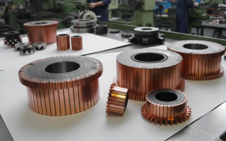
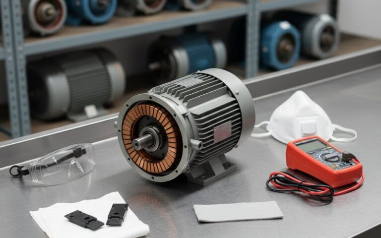
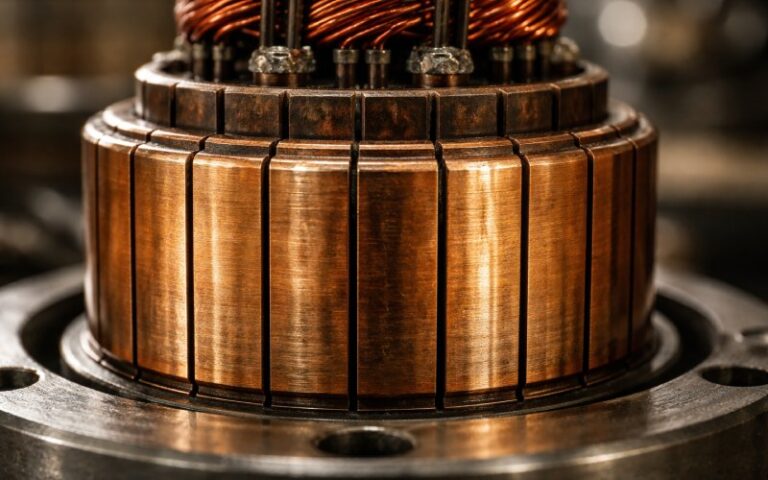
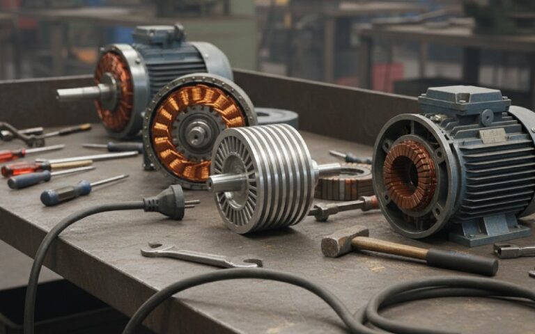
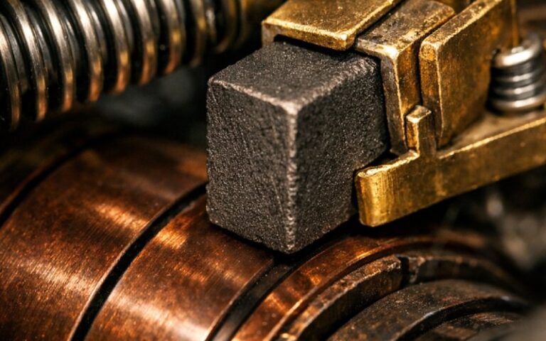
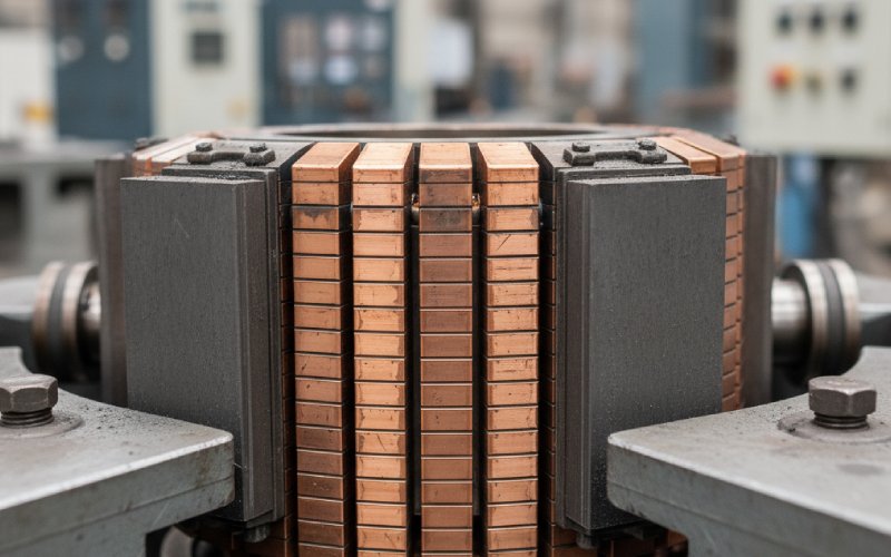
Inside a DC motor or generator, the commutator lives on the shaft. Segmented copper rings, carbon brushes sliding, constant switching as the rotor turns. It rectifies right at the armature, so the external terminals see mostly one polarity even though each coil is seeing alternating current as it spins in the field.
A rectifier sits off to the side — in a panel, a power shelf, a CP skid, a drive cabinet. It just watches the incoming AC waveform and forces it through diodes or controlled devices so that current flows in only one direction at the DC bus.
So:
- Commutator = rectification in the moving part of the machine.
- Rectifier = rectification in the fixed power electronics.
This alone changes how you buy, inspect, and replace them.
3. How the difference hits your project (not just your schematic)
3.1 Maintenance and downtime
Commutator realities
- Surface condition shifts with load, humidity, brush grade, vibration.
- Wear is gradual but visible: bar burning, grooving, high mica, out-of-round.
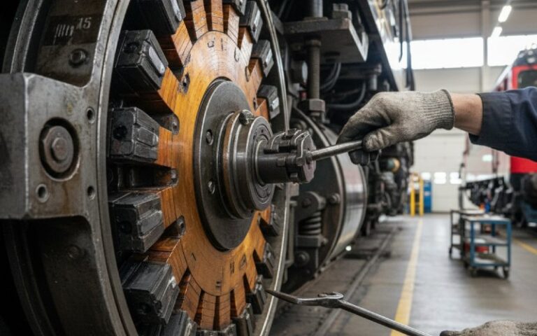
- Maintenance is labor-heavy: undercutting, skimming, reseating brushes, cleaning carbon dust, checking spring pressure.
Rectifier realities
- No moving parts, but they run hot and often close to rated current.
- Failure is usually binary: a diode opens or shorts, and the DC bus goes noisy or collapses.
- Health checks are mostly electrical: ripple measurements, thermal scans, stack tests, breaker checks.
If your site hates scheduled mechanical work but is okay with swapping a power module occasionally, you lean away from heavily brushed DC machines and towards electronic rectification plus brushless designs.
3.2 Sizing and derating: where the heat really goes
With a commutator, heat comes from:
- Armature copper loss
- Contact drop at the brushes
- Friction between brush and segment
Too aggressive a current density and you get sparking, copper drag, and brush wear. Your commutator supplier’s data on peripheral speed, segment pitch, and brush grade suddenly matters more than the brochure torque curve.
With a rectifier, heat is concentrated in the junctions and the baseplate. Modules like 100–400 A, 1600 V three-phase bridges are basically big blocks of silicon on metal plates that must be bolted to something that can move heat away.
The difference:
- Oversize a commutator and you pay in rotor diameter and inertia.
- Oversize a rectifier and you pay in enclosure space and a bit of cost, but your mechanics stay the same.
3.3 Where each one fits in a system diagram
Take a simple industrial DC drive for a rolling mill or hoist:
- AC mains → transformer
- Transformer → power rectifier (thyristor/diode bridge)
- DC bus → DC motor terminals
- Inside the motor → commutator + brushes
The rectifier shapes the DC bus seen by the motor; the commutator shapes the current inside the armature bars and keeps torque going in the right direction.
You can remove one or the other, but not casually:
- Replace the rectifier with pure AC → DC motor no longer has a DC supply.
- Remove the commutator from a brushed motor → it stops being a DC machine as you know it.
4. Comparison table: commutator vs rectifier
Use this when you’re debating drive architecture or talking to a new supplier.
| Aspect | Commutator (mechanical) | Rectifier (electronic) | What this means in practice |
|---|---|---|---|
| Location | On the rotating armature of DC motors/generators | In a stationary power circuit, usually panel-mounted | Different teams own them: mechanical maintenance vs electrical/power-electronics crew. |
| Main job | Reverse current in rotor coils; act as mechanical rectifier for induced AC | Convert AC line (or transformer secondary) to DC bus | Similar functional goal, but at different points in the chain. |
| Physical form | Copper segments, insulated, with carbon brushes riding on the surface | Diode/thyristor stacks, bridge modules, often resin-potted on a heatsink | One wears by rubbing, the other ages thermally and electrically. |
| Failure style | Gradual degradation: sparking, noise, brush wear, rough running | Often sudden or hidden: diode short/open, blown fuses, high ripple | Commutator gives you visual early warning; rectifier often needs monitoring instruments. |
| Maintenance | Regular inspection, resurfacing, brush replacement, cleaning | Periodic electrical checks, thermal scans, tightening, occasional module swap | Opex profile is very different; plan labor accordingly. |
| Typical applications | Traditional DC motors, generators, universal motors | Power supplies, DC drives, battery chargers, cathodic protection rectifiers | Your supply chain will be different: motor shops vs power-electronics vendors. |
| Scalability to high power | Limited by commutation at high current and speed, brush arcing | Easier to scale with bigger modules, series/parallel stacks, better cooling | Very high power systems usually shift rectification out of the machine. |
| Diagnostic tools | Stroboscope, vibration/EMI checks, visual inspection, brush wear gauges | Oscilloscope on DC bus, ripple meters, IR camera, insulation testers | Different skill sets and gear for your maintenance team. |
5. Where people try to substitute… and why it’s not that simple
A classic question: “Why not use a rectifier instead of a commutator?” You’ve probably seen that one on forums.
The short version:
- A commutator doesn’t just rectify. It rectifies synchronized to rotor position so the torque remains in one direction.
- A rectifier only cares about input voltage polarity over time, not where the rotor happens to be.
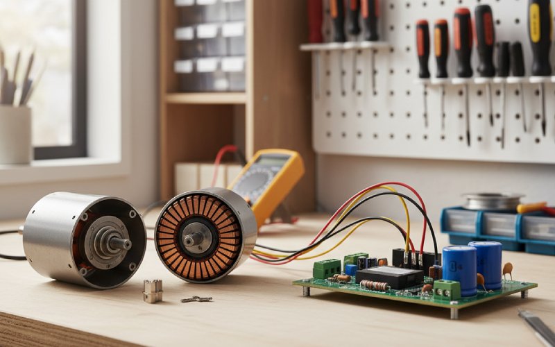
If you want to get rid of the commutator, you move to electronic commutation:
- Use a brushless DC motor or permanent-magnet synchronous motor.
- Put position sensing (Hall sensors, encoders).
- Let an inverter/drive handle both rectification and commutation logic.
Now the “commutator” is really firmware and IGBTs. The mechanical piece disappears, but a rectifier alone doesn’t replace it.
6. Buying decisions: what you actually ask vendors
6.1 Questions for a commutator (and motor) supplier
When you’re sourcing DC motors/generators with commutators, the helpful questions are not “Is it high quality?” but:
- What commutator design: number of segments, material, method of attachment to shaft?
- Recommended brush grade and specific current density limits.
- Maximum safe peripheral speed and temperature rise at rated load.
- Service procedures: how many skim/regrind cycles are acceptable before replacement?
- Available on-site support or field balancing options for large machines.
These answers tell you how often your plant will be opening motor end-bells.
6.2 Questions for a rectifier supplier
For rectifier stacks and modules:
- Topology: single-phase bridge, three-phase bridge, controlled rectifier with thyristors, or something more complex?
- Surge rating and overload capability (short-term vs continuous).
- Recommended heatsink Rθ, airflow or coolant requirements, mounting torque.
- Protection scheme: fusing, MOVs, snubbers, monitoring contacts.
- Field maintenance practices: how they recommend checking health in service; what failures look like in measurements.
Different questions, because the risk profile is different.
7. Strategy: when to live with commutators, when to move to electronic rectifiers only
You don’t pick between “commutator or rectifier” in a vacuum. You pick an architecture.
Typical patterns:
- Legacy plant, heavy DC motors already installed
- Keep commutators.
- Modernize upstream rectifiers (replace old mercury-arc or selenium with solid-state bridges/thyristor stacks).
- Add monitoring on both commutator condition and rectifier ripple to protect the investment.
- New line, wide speed range, tight process control
- Consider brushless machines plus rectifier/inverter front-end.
- You still have rectifiers (inside the drive), but commutators are now electronic.
- Harsh environment, poor access for mechanical work
- Every scheduled brush change is a logistical event.
- Pushing rectification into cabinet-mounted electronics and avoiding commutators reduces work near the load itself.
- Very high current DC (large electrolysis cells, CP systems)
- Rectifiers are central; machines may only be a tiny part or absent.
- Mechanical commutation rarely makes sense at these levels; you scale rectifier stacks instead.
Once you see the system this way, the phrase “difference between commutator and rectifier” becomes less about definitions and more about where you want to carry complexity: rotating steel or bolted silicon.
8. FAQ: difference between commutator and rectifier
1. Is a commutator a rectifier?
Functionally yes, but mechanically. In DC generators, the commutator converts the AC induced in armature conductors to a unidirectional output, so it works as a mechanical rectifier. However, it also synchronizes switching with rotor position, which a basic diode rectifier does not do.
2. Why use a commutator in DC machines instead of an external rectifier only?
Because the torque direction depends on the relationship between rotor current and magnetic field. The commutator flips current at the right mechanical angle. An external rectifier only looks at the line voltage over time; it has no information about rotor position.
3. Are rectifiers maintenance-free compared with commutators?
No. They avoid brushes and mechanical wear, but they still need inspection:
Verifying output voltage and ripple
Checking temperature and tightness of power connections
Testing diode/thyristor health during shutdowns
They fail differently, often by thermal or electrical overstress.
4. Can I retrofit a brushed DC motor to eliminate the commutator and keep only a rectifier?
Not practically. You would be redesigning the machine into a different motor type (BLDC or PMSM) with electronic commutation. That means new windings, rotor, drive electronics, and usually a different mechanical interface.
5. For a new project, what’s the simplest rule of thumb?
If you are locked into existing brushed DC machines, you must care about commutator design and service, and you add rectifiers upstream as needed.
If you are starting fresh and have budget for drives, it often makes sense to remove mechanical commutation entirely and let power electronics and rectifiers handle all the switching.