Commutator Undercutting Tool: Where Brush Life Is Really Decided
If your commutator undercutting tool can hold depth, keep the slot walls clean, and leave a predictable edge on the bars, your DC machines will usually stay quiet, stable, and boring. Most of the chronic arcing, brush chipping, and premature rewinds people complain about are just echoes of a tool choice made months or years earlier.
Table of Contents
What the documentation leaves between the lines
You already know the textbook rules: recess the mica a controlled amount below the copper, do not widen the slots, do not leave slivers, and do not score the bar edges. Typical guidance is in the region of about 0.025 to 0.032 inch below the commutator surface, with strict warnings against removing metal and against leaving thin mica edges that will break out later.
Standards and manuals also stress that recess depth should not exceed the mica width, and that every trace of mica must be cleared from the slot walls because a thin remaining strip can cause more trouble than a visibly proud section. These rules are simple. The hard part is choosing and using a tool that lets an actual technician obey them at real-world speed, inside cramped housings, with aging bearings and less-than-perfect fixturing.
That is where the undercutting tool, not the procedure, separates solid maintenance from chronic rework.
The main families of commutator undercutting tools
Most public material talks about “undercutting” as if it were one operation. In practice, the industry is running several different tool philosophies side by side: hand scrapers, small portable machines, bench or lathe mounts, and fully automatic indexed equipment. On the fringe there are abrasive-jet processes and other special methods.
To keep things concrete, here is a compact comparison that assumes you already know the basic process and care mostly about behavior on the shop floor.
| Tool type | Where it makes sense | Typical weaknesses |
|---|---|---|
| Hand tool based on modified hacksaw blades or scrapers | This approach works well when you have only occasional small armatures, good access, and an operator with the patience to feel every slot; it shines on one-off repairs and historic or specialty machines. | It depends heavily on operator skill, can be slow, and makes it easy to produce inconsistent depth or a slot that wanders or tapers from one end of the commutator to the other. |
| Handheld power undercutter with saw or wheel | This tool is useful when you need reasonable throughput on a wide range of armature sizes, possibly in situ, and want something that one technician can carry to the job. | It can chatter or walk if the support is poor, the cutter can be overspeeded or misapplied, and depth control depends on fixtures and discipline rather than inherent geometry. |
| Bench, lathe-mounted, or close-cut undercutter | This arrangement suits shops that already turn commutators between centers and want depth control tied to the lathe carriage; it is comfortable for small and medium machines with frequent rework. | It still consumes setup time, tends to struggle with very large or very small commutators, and relies on manual indexing or simple stops for bar-to-bar repeatability. |
| Fully automatic indexed machine with integrated cutters | This class fits motor repair facilities and OEMs that run many similar armatures and care about consistent undercut profile, chamfer, and cycle time, sometimes in the same machine that turns and brushes. | It locks you into specific cutter systems, adds capital cost, and shifts the problem from hand skill to program configuration, fixturing, and control maintenance. |
| Abrasive-jet or special processes | These methods are useful where physical tool access is difficult or where you want very gentle action on the copper while still recessing softer insulation. | They are niche, sensitive to media and shielding, and rarely justified unless you have a very particular commutator design or contamination risk. |
Once you see the family your operation sits in, you can stop asking “What is the best undercutting tool?” and start asking “What is the least chaotic tool that fits this context?”
Geometry choices: slot shape, chamfer, and depth control
Most manuals quietly assume a U-shaped or square slot: straight walls, a flat bottom, and a separate step to break the bar edges. In practice, tool geometry pushes you toward specific shapes whether you intend it or not. Thin saw blades like those in many Kut-Kwik style undercutters tend naturally toward a U or narrow rectangular slot, while some multi-edge cutters on automatic machines are able to cut undercut and chamfer in one indexed pass.
Forum discussions and EASA-oriented training material have been critical of pronounced V-shaped undercuts, particularly when technicians rely on them to combine recessing and chamfering in one aggressive cut. The concern is simple: to get enough depth, a V-cut tool removes too much copper from the bar sides, leaving deep grooves and fragile edges, especially on higher speed machines.
A practical way to think about geometry is to break it into three linked decisions. First, pick a tool that can achieve the specified recess depth without creeping wider than the mica. Second, decide whether you want the chamfer to be implicit in the cutter profile or created as a separate operation with a scraper shaped to a V and a slight rake. Third, enforce a single reference for depth: a mechanical stop, an indexed CNC program, or at least a gauge block and recorded setting. Mixing depth references within one shop is how mixed-slot commutators happen.
Mechanics of the cut: speed, rigidity, and wheel choice
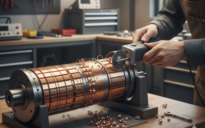
Once the geometry is defined, the physics of the undercutting tool starts to dominate the outcome. Portable air and electric undercutters show this clearly. Martindale’s Kut-Kwik range, for example, covers air-driven units around 4000 and 5300 rpm for high-speed steel and carbide saws, then pushes to 20,000 rpm and beyond for diamond wheels, with a dedicated 35,000 rpm mini undercutter for very tight spaces. High speed gives a smooth cut and shorter cycle time, but only if the commutator support and operator grip are rigid enough to prevent chatter.
Automatic undercutting machines from makers such as Rimac add a different layer: micrometric cutter positioning, automatic bar search and indexing, and programmable depth variation along the commutator face. Instead of hand feel, you get an axis control system deciding where the cutter sits at each bar, including variations at the ends where brush loading might justify a slightly different profile. When this works, the result is impressive consistency; when it drifts, you can repeat the same mistake hundreds of times in one batch.
For hand tools and lathe attachments, the mechanics are humbler but just as important. A ground hacksaw blade with the set removed, a rounded working tip, and a comfortable handle can produce surprisingly consistent slots if the user works radially and keeps pressure light. The absence of vibration is the feature; the low metal removal rate is the price. In many small shops, that trade is acceptable.
Wheel and blade material should be chosen with operator behavior in mind, not just catalog life. Carbide saws cut fast but are brittle and demand a steady hand; diamond wheels on a high-speed tool are efficient but expensive, so they tempt people to push them into jobs where fixturing is marginal. High-speed steel is more forgiving when the setup is shaky, even though it wears quicker.
What good undercutting actually fixes in the field
Renown Electric’s service notes, among others, point out the obvious but often ignored link between proper turning and undercutting, uniform brush wear, and reduced arcing, vibration, and excessive commutator wear over the life of a DC motor. HECO’s failure data from hundreds of industrial clients shows commutator wear and brush-related issues as key electrical failure modes, commonly associated with grooved, burned, or uneven commutator surfaces. Their recommendations explicitly include proper turning and undercutting as part of avoiding overheating and premature failures.
From a tool-centric viewpoint, recurring symptoms can often be read backward into tool choices.
If you see undercuts that vary visibly in depth around the circumference, you are probably looking at a handheld undercutter without a dependable depth reference, or a lathe attachment being operated by eye alone. If the slots have ragged walls and stubborn mica slivers, it suggests a cutter profile that does not match the mica width or a tool that is being dragged off angle, which is common when improvised hand tools are too wide for the slot.
When bar edges chip during early operation, especially on higher speed machines, suspect aggressive V-shaped cuts or over-deep undercuts. Deep recesses of several millimetres have been reported in practice, and they are difficult to correct without heavy re-machining. That is not a process failure so much as a tool geometry failure: the tool made it easy to remove too much copper while chasing “clean” slots.
Finally, where the commutator surface looks fine but you still get bad commutation, uneven brush tracks, or vibration, it is worth checking whether the undercutting tool left burrs on the bar edges that were never removed. Manual accounts repeatedly stress the importance of dressing the commutator after undercutting, removing burrs with abrasives that do not embed hard particles in the copper and carefully cleaning debris from the recesses. If your tool choice or process makes that step awkward, it will quietly stop happening.
Buying and specifying undercutting tools with fewer regrets
Once you no longer treat all undercutters as equivalent, specification becomes less about price and more about where error is allowed to live. With a simple hand tool, uncertainty sits in the technician’s hands, but the device itself is transparent. With a portable power undercutter, uncertainty shifts into fixturing, wheel selection, and speed control. With a fully automatic machine, most uncertainty moves into software parameters, calibration, and feedback devices.
For a small repair shop handling varied legacy equipment, one common pattern is to pair a reliable lathe setup for turning with a modest power undercutter that can be guided from the same centers, plus a set of carefully ground scrapers for final wall cleaning and chamfering. This combination gives you mechanical references instead of pure hand aiming, but avoids the complexity of a full CNC undercutting cell.
Larger facilities with recurring armature types and serious throughput expectations tend to justify automatic machines that combine turning, undercutting, brushing, and sometimes welding or banding in one fixture. Rimac, for instance, promotes automatic bar search and indexing, multiple undercutting programs, and integrated edge-rounding units that cut and chamfer in one controlled cycle. If you go this route, budget mental energy for the commissioning phase; the machine is only as good as the profiles you teach it.
There is also a very practical middle ground: high-speed portable undercutters with diamond wheels, mounted on purpose-built stands or guides that constrain position and angle relative to the commutator. Martindale’s portable electric Kut-Kwik with a flexible drive shaft is one example that tries to balance reach with control. These setups can be tuned to specific motor families and still stay mobile enough for field work.
Building a repeatable routine around the tool you have
The tool you pick is not the end of the story; it is the constraint under which you design a routine. A realistic routine for any undercutting setup tends to have a few shared features, even if the steps look different.
First, there is always a way to verify depth that does not depend on “looks right.” That may be a feeler gauge slid into the recess at several bars, a microscope with a calibrated reticle, or a low-tech but consistent comparison block. Given how tight the recommended depth band is relative to commutator diameter, this check is not optional.
Second, there is a defined approach for dealing with the slot walls and bar edges after the main cut. Manuals emphasise that the walls must be free from mica remnants and that the edges should be bevelled by about half a millimetre at 45 degrees, often using a small scraper shaped to a V, followed by careful cleaning of copper debris by brushing and vacuuming. Whether you achieve this with a dedicated chamfering attachment or a manual scraper, it needs to be explicit in the process.
Third, your routine ought to include a feedback loop from motor performance back to tool settings. If a certain undercutter setup repeatedly precedes arcing or brush striping on a specific motor type, that is a tool problem revealing itself through field data, not “operator error” in isolation. HECO’s failure analysis approach is a good reminder that commutator issues rarely exist on their own; they link to ventilation, load, brush material, and system design. When you adjust the undercutting tool, you are adjusting one element in that whole chain.
Closing thoughts
A commutator undercutting tool is just a device that removes a thin, stubborn strip of insulation. On paper, that sounds trivial. In practice, the way it controls geometry, loads the operator, and interacts with fixturing has long-term consequences for brush life, downtime, and how often you have to revisit the same machine.
If you already know the official numbers and textbook procedures, the useful question is no longer “How do I undercut?” but “Given the motors I see, the access I really have, and the people who will actually run this, which tool will quietly give me the least spread in slot depth and edge condition?”
Answer that honestly, and the undercutting step stops being an adventure and becomes what it should be in a DC maintenance program: a small, controlled, almost dull operation that leaves nothing interesting behind.