OEM Commutator Test Procedure: Factory QA and Incoming Inspection Checklist
A commutator should not reach assembly just because it looks clean.
In our factory, the test sequence starts before the first electrical reading. Surface first. Geometry next. Insulation after that. Then segment consistency. Then sample validation in running condition. That order stays. It saves time, and it catches the defects that matter before they become brush trouble, heat marks, or warranty noise.
This article shows the commutator test procedure we use for new parts before shipment, and the same checklist many buyers use again as incoming inspection before motor assembly.
Table of Contents
Factory Commutator Test Procedure at a Glance
| Test Step | What We Check | Factory Release Rule | Main Risk if Ignored |
|---|---|---|---|
| Visual surface check | Copper face, slot cleanliness, edge damage, contamination | No drag marks, no copper smear, no loose debris, no lifted segment edge | Early sparking, uneven film, brush wear |
| Dimensional inspection | OD, ID, length, segment pitch, bore fit | Must match drawing and batch tolerance | Assembly mismatch, balance shift, poor concentricity |
| Runout test | Radial runout after final machining | Controlled to drawing limit; for many standard builds, TIR is kept within 0.002 in | Brush bounce, local heating, unstable commutation |
| Mica undercut check | Depth, width, slot cleanliness, edge chamfer | Uniform undercut, clean slots, no high mica | Brush chipping, edge burning, copper pickup |
| Segment retention check | Bar security, resin or molded support integrity | No movement, no crack propagation, no seating weakness | Lifted bars, mechanical failure at speed |
| Bar-to-bar consistency | Adjacent segment electrical uniformity | No short path, no abnormal resistance spread | Circulating current, hot bars, poor load sharing |
| Bar-to-shaft insulation | Isolation from shaft or core path | Must meet insulation requirement of the design | Ground fault, leakage, carbon tracking |
| Sample running validation | Brush track formation and contact pattern | Stable track, no abnormal sparking trend | Field failure after assembly |
1) Visual Inspection Comes First
Not every defect deserves a meter. Some deserve a reject tag first.
We start with the copper face and the slot wall. On a new commutator, the things that matter are simple:
- copper surface condition
- slot cleanliness
- segment edge integrity
- molding or support condition
- signs of handling damage during storage or transport
If we see copper smear across the slot, segment edge lifting, chipped insulation, embedded debris, or impact marks near the bar corners, the part does not move forward as a normal release lot.
A clean face is not enough, either. We want a uniform machined finish, no dragged copper, no raised edges, no residual particles packed into the slot. Very small defects at this stage tend to become very visible once brush contact starts. Not immediately. A little later.
For buyers doing incoming inspection of a new commutator, this is the fastest screening step. Good parts usually pass it in minutes. Bad parts also tell on themselves in minutes.
2) Dimensional Inspection Must Match the Drawing, Not Habit
A lot of avoidable assembly problems come from this step being treated as routine.
We verify:
- outside diameter
- bore or mounting diameter
- overall length
- segment count and pitch consistency
- key assembly dimensions that affect press fit, clamp fit, or molded seating
- stack relationship if the commutator is supplied as part of a rotor assembly
There is no universal “acceptable” dimension set for all commutators. The drawing is the rule. Still, we pay extra attention to dimensions that alter brush path geometry and shaft fit. Those are the dimensions that keep causing secondary problems while looking harmless on paper.
For OEM lots, we also compare within-batch consistency, not only single-piece compliance. A part that passes alone but drifts from the batch center is still a process warning.
3) Runout Testing Decides Whether the Part Will Behave Under Brush Contact
This is one of the most practical checks in the whole process.
After final machining, we measure radial runout on controlled support points. The exact limit follows the product drawing. For many standard builds, we hold total indicated runout within 0.002 in after finish machining. Tighter builds may require less. High-speed duty usually does.
Why does this matter so early? Because brush instability often gets blamed on grade, pressure, or spring setting when the real issue is geometry. A commutator that is not running true can still look acceptable on the bench. Once installed, it stops being subtle.
If a buyer is checking a newly received part, this is one of the best tests to separate a serious manufacturing supplier from a loose one.
4) Mica Undercut and Slot Condition Need Their Own Inspection
We do not bury mica undercut inside “visual check.” It gets its own step.
On undercut designs, we inspect:
- undercut depth
- undercut width
- slot uniformity around the circumference
- slot cleaning quality
- bar edge condition after machining
- light chamfer condition where required
As a baseline shop rule, when a specific drawing does not override it, we keep undercut width and depth proportional to the mica thickness, and the bar edges are kept clean with a controlled chamfer. Too shallow and the brush starts riding insulation. Too aggressive and segment support is reduced. Both are bad. Just different timing.
High mica is a common reason for edge burning on startup. Dirty slots are another. Neither should leave the factory.
5) Segment Retention Is a Real Test, Not a Visual Guess
A commutator can pass dimensional inspection and still fail because the segment package is not mechanically stable.
So we check for:
- segment looseness
- cracked support material
- seating weakness near the neck or riser zone
- movement under controlled mechanical verification
- signs of stress concentration from molding, pressing, or machining
For critical applications, we review retention performance together with process traceability. Not only the finished piece. The process behind it.
From a buyer’s side, any sign of segment lift, resin fracture, bar instability, or suspicious movement near the copper support zone should move the part out of normal assembly flow. A new commutator is not the place for hopeful decisions.
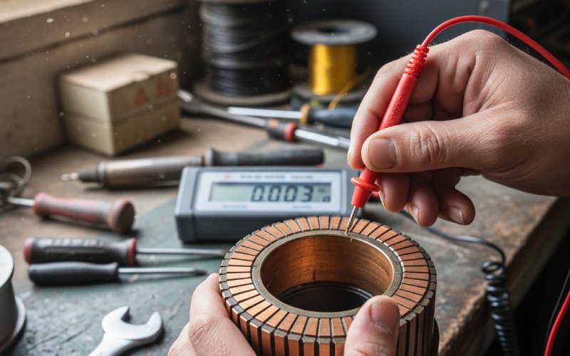
6) Bar-to-Bar Testing Confirms Electrical Separation and Uniformity
Now the meter belongs on the part.
We check adjacent segments for abnormal continuity paths and verify electrical consistency around the circumference. Depending on design and test method, this may include:
- adjacent-bar separation check
- low-resistance comparison
- resistance trend review across the segment circuit
- sample-based deeper validation for controlled lots
We are not looking for one magic number. We are looking for uniformity and for absence of unintended connection. A single abnormal pair matters. So does a repeating pattern every few bars. Patterns tell you whether the defect is isolated, process-based, or built into the tooling behavior.
This is one reason batch history matters. Good factories do not just test a commutator. They read the process through the result.
7) Bar-to-Shaft Insulation Testing Protects the Whole Assembly
This step verifies insulation integrity between the conductive commutator structure and the shaft or any grounded path defined by the design.
Our test sequence usually includes:
- insulation resistance measurement
- dielectric withstand verification where required by the product spec
- controlled retest protocol for suspect parts
- contamination review before any repeat test is allowed
A poor insulation result is not always a material problem. Sometimes it is contamination. Sometimes moisture. Sometimes handling. But the cause does not change the release decision. If the part does not meet the insulation requirement, it is blocked.
For incoming inspection teams, this check is especially useful for parts destined for high-voltage, dusty, or variable-humidity service.
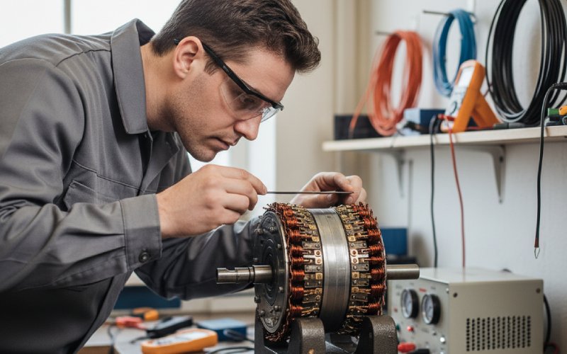
8) Sample Running Validation Still Matters
Even strong bench data can miss what brush contact reveals in motion.
So for selected lots, prototype builds, or critical programs, we validate the commutator in running condition and review:
- brush contact pattern
- early track formation
- sparking trend
- edge behavior at load transition
- local heat signature if the build requires it
We do not force full-load confidence from a static test sheet. A commutator has to behave in the motor, not just on the table.
For new brush contact, we look for a stable, developing track and a meaningful seating pattern before duty is increased. A face with poor contact distribution may still run. For a while. That is not the same as release quality.
Incoming Inspection Checklist for New Commutators
When our customers receive a new commutator, this is the shortest practical inspection path we recommend before assembly:
- Check surface finish, slot cleanliness, and segment edges
- Confirm key dimensions against the approved drawing
- Measure runout on proper support points
- Inspect mica undercut and edge condition if applicable
- Verify segment stability and support integrity
- Check adjacent-bar electrical consistency
- Check bar-to-shaft insulation
- Approve only after lot identity and traceability match the order
If the part fails at step 1, 3, 5, or 7, we do not suggest forcing it into assembly. These are not cosmetic misses.
When a New Commutator Should Be Rejected, Not “Worked Around”
Some problems should not be pushed downstream.
We recommend rejection or formal hold when you find:
- excessive runout
- segment lift or unstable bars
- cracked insulation support
- abnormal adjacent-bar electrical reading
- weak bar-to-shaft insulation
- high mica or poor slot cleaning on finished parts
- transport damage near bar edges or mounting surfaces
- batch inconsistency that suggests process drift
This part matters: a questionable new commutator should not be treated like a field-repair candidate. If the defect is already present before assembly, the lowest-cost decision is usually made early.
What This Test Procedure Shows About the Supplier
A commutator supplier should be able to do more than quote dimensions and copper grades.
A serious manufacturer should be able to tell you:
- how runout is controlled after final machining
- how segment retention is verified
- how insulation is tested and recorded
- how batch consistency is monitored
- how nonconforming parts are blocked
- how traceability is maintained from material to finished lot
That is the real use of a commutator test procedure in B2B supply. Not decoration. It shows whether the factory is controlling the product or merely shipping it.
Need a Replacement Instead of a Risky Build?
If your inspection shows unstable segments, insulation failure, repeat runout issues, or slot defects that should not be accepted in a new part, replacement is usually the cleaner decision.
We supply OEM and custom commutators built around the same test logic described above: dimensional consistency, stable segment structure, controlled runout, verified insulation, and batch-level quality records. For new motor programs, rebuild supply chains, or incoming inspection upgrades, that matters more than polished wording.
FAQ
What is the standard commutator test procedure for a new part?
For a new commutator, the practical sequence is: visual inspection, dimensional check, runout test, mica undercut inspection if applicable, segment retention verification, bar-to-bar electrical check, bar-to-shaft insulation test, and sample running validation where required.
What is the most important test during incoming inspection?
There is no single test for every build, but three checks usually catch the highest-risk issues early: runout, segment stability, and bar-to-shaft insulation. If any of those fail, assembly should stop.
What runout is acceptable for a commutator?
The correct limit depends on the drawing and the motor duty. For many standard commutators, total indicated runout is controlled within 0.002 in after final machining. Precision or high-speed applications may require tighter control.
Why does a new commutator fail even though the dimensions are correct?
Because dimensional compliance alone does not prove electrical separation, insulation integrity, slot quality, or segment stability. A part can match the drawing and still fail in service.
Should a buyer test bar-to-bar resistance on every incoming lot?
For controlled programs, yes. At minimum, buyers should have a defined sampling plan for adjacent-bar consistency and insulation verification, especially for OEM production or critical service environments.
How do you know whether a commutator defect is cosmetic or functional?
If the defect changes geometry, insulation, segment stability, slot condition, or brush contact behavior, it is functional. Marks that only affect appearance and do not alter those factors may remain cosmetic. The line between the two is not wide.
Can a new commutator with high mica still be assembled?
It should not be released as-is. High mica changes brush contact and can trigger edge burning, uneven wear, and unstable track development very early in service.
What should a good commutator supplier provide with the product?
At minimum: drawing compliance, batch identification, quality records for critical checks, and a clear acceptance standard for runout, insulation, and segment integrity.