Commutator Switch: Quiet Mechanics Behind Direction and Duty
A commutator switch is just a timed change of contact on copper and carbon, but the way you specify it, wire it, and age it decides whether your machine keeps turning years from now or stops with a blackened segment and a tripped breaker.
Table of Contents
Beyond the textbook definition
You already know the formal story: a commutator is a rotary electrical switch that reverses current in DC machines or picks off current in generators, and that similar contact blocks show up in cam and rotary selector switches in control panels. The documentation explains the geometry, the voltage, the insulation material. It does not really talk about the odd sounds on startup, the one pole that always runs hot, the way a “simple” commutator switch in an appliance or panel becomes the most blamed part in the stack.
Most web articles on commutator switches stop at naming types and listing generic uses in lighting, machine tools, and home appliances. That is useful once. After that, what you need is a view that connects catalog numbers to the actual job in front of you, including the messy stuff: uneven wear, contamination, nuisance tripping, and replacement decisions when brushless or electronic options are available.
Where commutator switches still make sense
Mechanical commutation has been pushed back by solid-state drives and brushless motors, but it has not disappeared. The common places it still appears are not exotic. Domestic and professional power tools, small universal motors in appliances, older DC traction or hoist systems, and industrial cam switches that select between positions like 0–1–2–3 or star–delta arrangements still rely on commutator-style switching blocks.
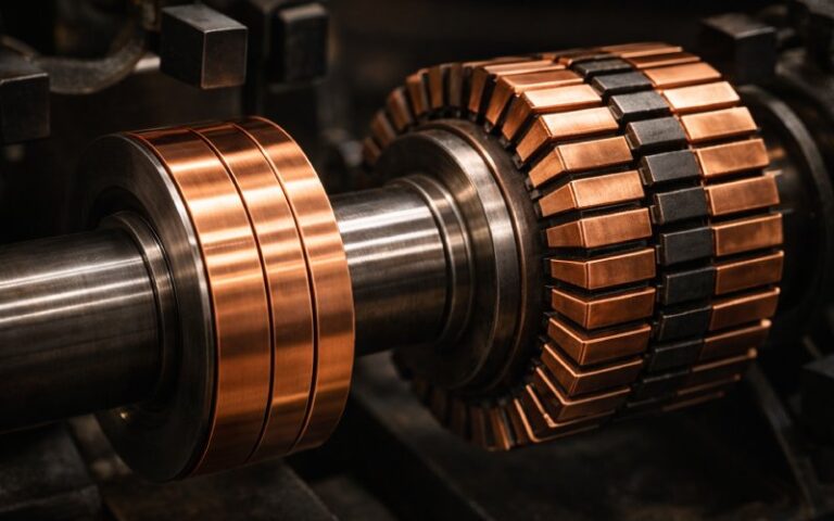
The reason is not romance for copper. It is that a shaped set of contacts on a shaft or cam offers a very compact way to encode timing and sequence in hardware. In a motor, the commutator links rotor position to current direction with a precision tied directly to geometry, so you get torque without external electronics. In a panel switch, a rotary commutator stack lets you map a simple knob position into quite intricate contact combinations with almost no quiescent loss and with instant visual feedback.
When you look at real installations, commutator switches tend to survive in three patterns. They survive where supply is harsh and electronics would need heavy protection anyway. They survive where maintenance staff is used to replacing brushes and contacts and would rather keep that habit than learn new diagnostic tools. They also survive in low-volume, specialized machines where redesigning to brushless or fully electronic control simply has not been worth the engineering cost.
Naming the thing correctly
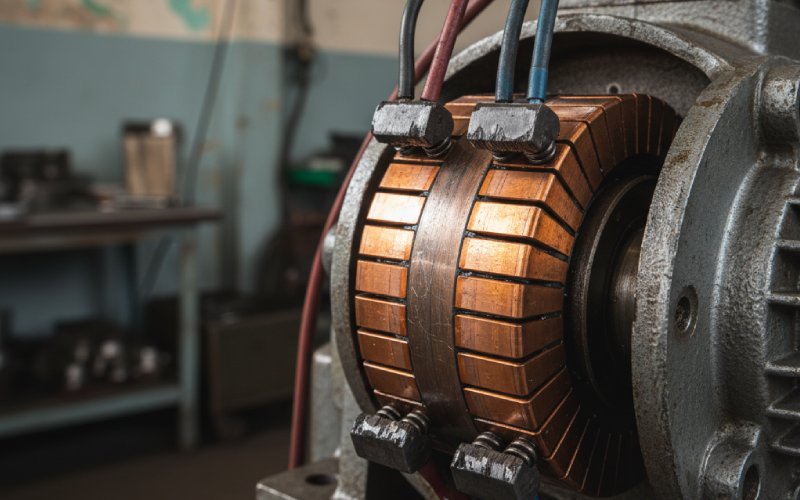
Language is slightly messy here. In DC machine theory, “commutator” normally means the segmented cylinder on the rotor, together with the brushes that ride on it. In switch catalogues, “commutator switch” or “commutator group” often describes a rotary or cam switch assembly that uses fixed segments and moving contacts to step through discrete positions, such as 0-1-2-3.
Functionally, both devices are about controlled contact changes over angle and time. The motor commutator enforces a strict schedule: every half turn, current in a coil reverses relationship to the field so torque stays roughly consistent. The panel-mounted commutator switch enforces a different schedule: every fixed knob position corresponds to a stable pattern of closed and open paths. From a design point of view, you are always asking the same questions: what gets connected to what, at which mechanical angle, under which current and voltage, and with what tolerance for misalignment, contamination, and wear.
Spec sheets without the marketing gloss
Vendor pages usually give you voltage rating, current rating, number of poles, number of positions, step pattern, mechanical life, electrical life, and sometimes switching diagram PDFs. That looks complete but hides several real-world choices.
The current rating is usually tied to a duty assumption. Many cam-type commutator switches are rated for AC-23 or DC-21 style categories, which assume certain power factors and make-break patterns. Those letters matter more than the headline ampere number, especially if you are interrupting DC under load, which stresses the contacts far harder than simply selecting between no-load measurement ranges.
Voltage rating is not just insulation thickness. On DC, the arc length you have to break is directly tied to how much contact separation you get before the mechanism snaps to the next segment. A switch that is perfectly safe switching 400 V AC can be very stressed at 220 V DC if the contact gap and blow-out geometry were not intended for it.
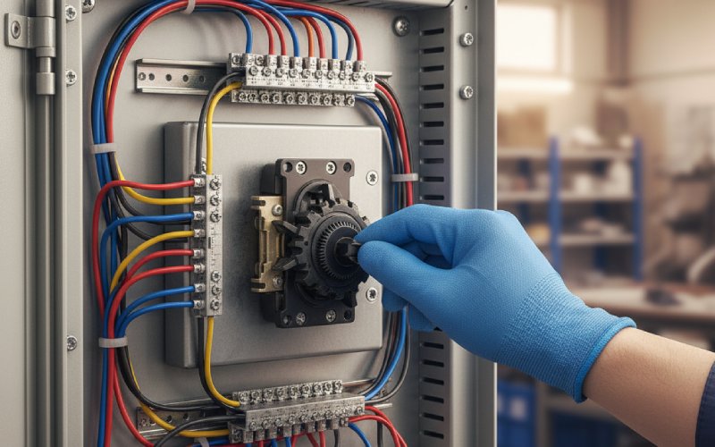
Number of poles and positions looks simple on paper, yet for complex functions like motor reversing, star–delta starting, or multi-range control, the internal bridging diagrams can get dense. This density is where mistakes happen, because a single wrong bridge sometimes creates a short-lived but severe short circuit as the handle moves between positions.
To make all this less abstract, it helps to look at the same device family through a more practical lens.
| Design aspect | What the datasheet tells you | What actually changes in practice | Subtle side effect you notice late |
|---|---|---|---|
| Current rating | A single number at a given utilization category | Cross-section of segments, brush size, spring force, and allowed temperature rise | Higher rating often means stiffer springs, which increases brush wear and audible noise |
| Voltage rating | Maximum system voltage, often different for AC and DC | Required isolation distance and contact opening speed | Using the switch near the top DC rating tends to increase contact erosion and makes arc chutes more critical |
| Number of segments or positions | Count of discrete steps and poles | Complexity of wiring and risk of mis-phasing or mis-bridging during design | Maintenance staff faces harder fault-finding because a small wiring error may only appear in one intermediate position |
| Mechanical life | Operations at no load | Quality of bearings, shaft, and cam surfaces | High mechanical life does not always equal high electrical life if your load is harsh and inductive |
| Electrical life | Operations at rated load and category | Wear pattern of contacts or commutator bars, erosion of edges | When combined with poor enclosure sealing, contaminants shorten electrical life far below the test figures |
Once you start reading spec sheets this way, device selection becomes less about “does the number match” and more about “can this mechanical geometry survive the task we are giving it.”
The physics you feel before you calculate
A commutator switch is not only copper and carbon; it is small pressure points, micro-arcs, and sliding films. Wikipedia talks about the “brush drop”, the voltage you lose at the sliding interface between brush and commutator segments. On low-voltage, high-current machines this drop can be several volts, which translates to meaningful power loss and heating. You can feel this, quite literally, as a warm brush holder or a hot spot on the housing near a panel-mounted commutator stack that runs near its limit.
Contact resistance fluctuates with contamination films, micro-welding events, and vibration. The user hears this as a faint crackling when switching under load, especially on DC, and sees it as a subtle jitter in analog readings when the commutator switch feeds a measurement circuit. Poor contact geometry or tired springs exaggerate this, and you get intermittent complaints long before outright failure.
Arcing is part of the physics, not an accident. When a commutator segment disconnects an inductive load, the current wants to keep flowing, air breaks down, and the arc stretches until the physical gap is too large. The switch designer shapes contacts and movement so this process finishes quickly and the energy is not concentrated in one location. In small household commutator switches, the arc is barely visible but still etches the metal; in DC motor commutators, heavy commutation under load can lose material at the edges of bars quite rapidly if brushes are not correctly graded.
All of this leads to one simple observation: when you hear or smell a commutator switch, you are usually listening to the parts of the design the spec sheet did not describe.
Typical failure stories and what they point to
Most public articles mention brush wear and commutator wear in general terms. In practice, the pattern of that wear tells a fairly specific story.
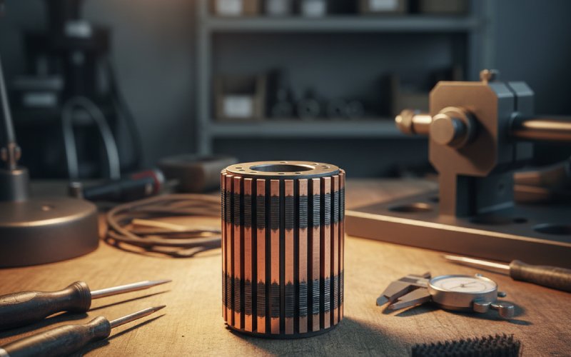
If you see a single commutator segment significantly darker or more damaged than its neighbours, it often means a systematic current imbalance or a mis-wired segment. In a cam-type commutator switch, this shows up as one position that always arcs more, often due to that step breaking the highest inductive load. Splitting the load or pre-switching a resistor sometimes moves that stress away enough to make the device last.
Uneven brush wear across the width of the commutator indicates misalignment or shaft issues. The brush face may only contact one edge of the bar ring, which increases current density and accelerates wear, although the motor still meets performance tests for quite a long period. You see a similar effect in small selector switches when the operating shaft is slightly bent; contacts scrape more intensely on one side of the cam, and failures cluster in that quadrant.
Contamination is its own category. Fine carbon dust, metal filings, or process dust can bridge segments or find their way into the switch body. Wikipedia notes that early copper brushes produced debris that could wedge between commutator segments and short them. Modern carbon brushes are better, but panel-mounted commutator switches in harsh industrial environments still suffer from this mechanism; the switch becomes both a selector and an unintended sensor of how dirty the enclosure really is.
Finally, thermal cycling slowly loosens screws, distorts plastic carriers, and changes contact pressure. A switch that was correctly torqued and aligned at commissioning may gradually shift, especially when mounted on thin doors or panels that flex. The result is a switch that appears electrically healthy on the bench yet misbehaves once bolted back into its real housing.
Choosing between mechanical commutation and electronic switching
Given that brushless motors and solid-state switches are widely available, it is reasonable to ask why someone would still specify a commutator switch for a new design. Technical sources point out that commutated machines are less efficient and need more maintenance, which is part of why many large DC machines have been replaced by AC or brushless equivalents.
Yet mechanical commutator switches can be quite attractive when you need:
A direct mapping from shaft angle to contact state with no sensing or firmware in between.
Predictable failure modes that are visible under inspection. Contact wear and discoloration are easy to interpret compared with intermittent semiconductor breakdown.
Low latency and low idle power. A mechanical switch at rest consumes nothing and adds almost no noise.
There is also the cost structure. In very small appliances where margins are tight and unit counts are high, manufacturers still use compact commutator-style switches or simple rotary selectors because they are cheaper than control electronics plus human-friendly interfaces. In retrofit scenarios, reusing the existing commutator switch location and wiring can avoid complete panel redesign.
On the other hand, electronic options bring their own advantages. Brushless DC drives remove mechanical commutators entirely by using sensors and semiconductor switches to control current direction, giving longer operating life and easier speed control at the expense of a more complex bill of materials. Solid-state relays and contactors handle high switching frequencies with no visible wear surfaces, which suits automated or remote-controlled systems. The trade is clear: more invisible complexity, less mechanical maintenance.
So the decision is rarely purely technical; it is a balance of skill sets, maintenance regimes, safety requirements, and cost of downtime.
Installation details that avoid slow failures
Manufacturers often provide installation notes, but some patterns repeat often enough that they are worth restating.
Panel flatness matters. A cam-type commutator switch mounted through a thin, slightly warped door can twist just enough that the rotor rubs unevenly on its segments. The operator feels extra stiffness at certain positions and naturally pushes harder, which speeds up wear exactly where geometry was already weakest.
Conduit entries and cable bending radii affect internal stress. Heavy cables that push sideways on the body of the switch create long-term mechanical bias, shifting clearances and alignment. In DC motors, cable strain near the brush holder can transmit vibration into the brush gear, changing contact pressure over time in a way that depends on how the cable was tied during the last service.
Environmental sealing interacts with heat. A tightly sealed enclosure protects the commutator switch from dust and moisture, which is good, but it can also trap heat from contact losses and nearby components. Electrical life figures are usually obtained under controlled temperature; real installations that run noticeably hotter will see faster contact oxidation and increased arc damage.
Grounding and bonding paths deserve real attention. A poorly bonded enclosure can leave the commutator switch structure floating at some unintended reference during transients. This is more of an issue in larger machines and high-energy DC systems, yet even small installations have shown strange behavior that disappeared once panel grounding was improved.
Treating maintenance as part of design
Once a commutator switch is in service, the maintenance plan effectively becomes part of the device design. Science and engineering references describe the need for periodic brush replacement and resurfacing of commutators on larger machines. For panel-mounted commutator switches, a similar pattern applies, although tasks are lighter.
If you assume zero maintenance, you must de-rate the device in design. That means lower currents, less frequent switching, or more robust parts than the bare calculation suggests. If you assume regular inspection, you should design physical access carefully: removable covers that do not disturb wiring, clear labeling of positions, enough room for a technician to see contact faces without dismantling half the panel.
Documentation quality also matters. Many commutator switch failures trace back to faulty wiring changes that were done years after commissioning by someone who did not have access to the original switching diagram. Providing those diagrams in a form that actually survives – printed inside the panel door, mirrored in a plant database, not just as a one-off attachment – is the kind of mundane decision that has real impact on device life.
Looking at commutator switches with a longer view
Once you strip away the textbook definition, the commutator switch becomes a very ordinary but still useful tool: a way to encode a relationship between movement and connection state in physical metal. Articles that only answer “what is a commutator switch?” stop at naming that tool. Articles that try to be more practical need to talk about how that tool ages, how it fails, and when it still justifies its space in a modern design beside electronic alternatives.
If you treat specifications as the starting point, not the whole story, and you read the device through its wear patterns and installation context, the commutator switch becomes easier to design with and easier to justify. Not spectacular, not obsolete, just a careful compromise between simplicity, contact physics, and how much mechanical work you want copper and carbon to keep doing for you.