Commutator Segment Mica
If the segment mica is right, the commutator usually behaves itself: bars stay where they should, brushes wear in a predictable way, and sparking stays boring. If it is wrong, no amount of brush tweaking or rewinding really fixes the motor for long.
Table of Contents
What segment mica is really doing for you
You already know the block diagrams and the standard formulas. So let’s skip that and talk about what the mica between segments actually has to survive.
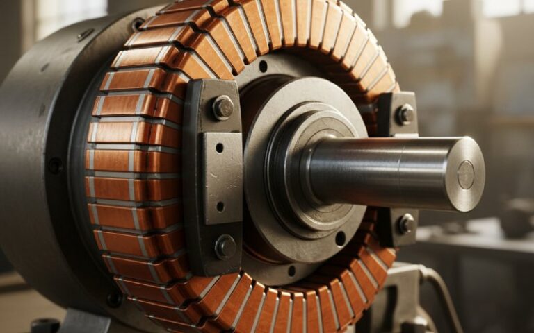
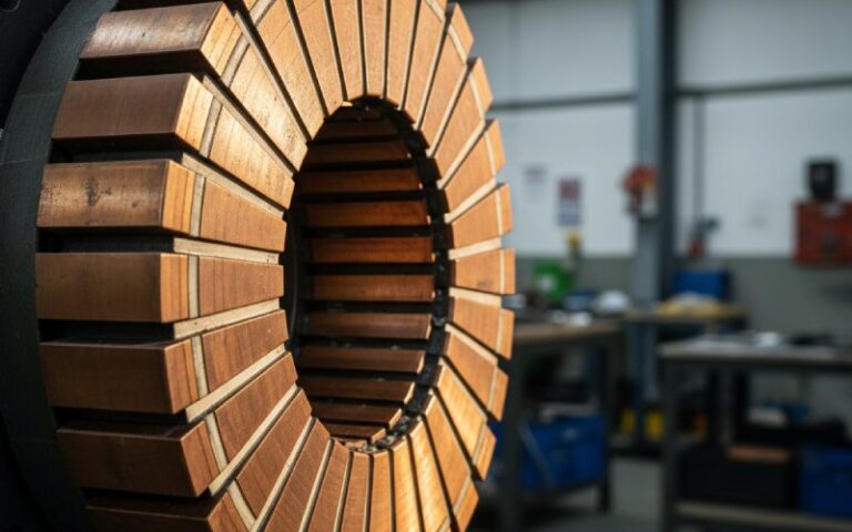
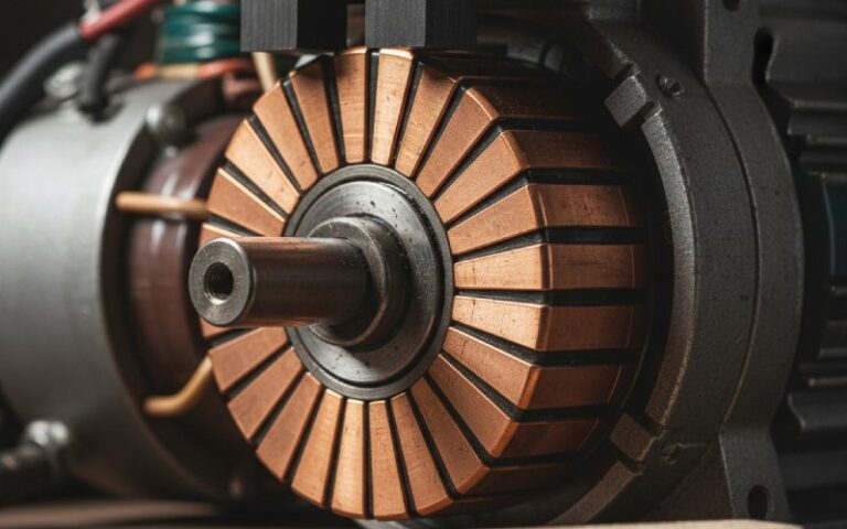
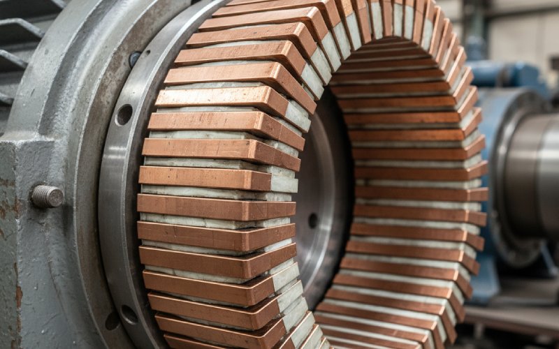
Each commutator bar is a wedge of hard-drawn copper, clamped into a cylinder and separated from its neighbours and the steel hub by insulation, most often segment mica. During operation, that insulation sees compressive stresses from clamping and centrifugal force, shear from torsion of the bars, cyclic heating from load changes, and local hotspots under the brushes. It has to maintain dielectric strength, stay dimensionally stable, and not crumble when you undercut it again ten years later.
On large DC machines, mica is still the standard between bars. Plastics show up in smaller motors, often as molded commutator bodies, but for big machines and traction-duty equipment, mica remains the conservative choice because it holds its shape and dielectric properties at temperature and pressure levels where most plastics start to creep.
So “commutator segment mica” is not just a filler between copper bars. It is a structural insulation system that sets the ceiling on speed, voltage, and how much abuse the machine can take before the commutator becomes the limiting factor.
What good commutator segment mica looks like in practice
Standard commutator mica sheets are usually built from natural muscovite splittings, pressed at high temperature with a relatively low amount of thermosetting resin. The goal is a dense, rigid plate where the mica platelets still carry most of the load, and the binder simply ties them together and cures without oozing.
The better grades show a familiar pattern of properties: high dielectric strength, thermal stability into the upper insulation classes, low compressibility, smooth surfaces, tight thickness tolerance, strong resistance to crushing, and good machinability. Low compressibility matters more than people sometimes admit; if the mica creeps under centrifugal stress, the commutator goes out-of-round, the brush track loosens, and your carefully machined concentricity slowly disappears.
Many suppliers work to NEMA 3-style segment plates: rigid mica, typically muscovite or phlogopite, bonded with shellac, alkyd-vinyl, epoxy or similar binders, in the 0.015–0.060 inch thickness range, with dielectric strength on the order of 550–650 V/mil and compression strengths up to tens of thousands of psi. That is a practical level of performance, not marketing gloss: it is what allows the segment pack to be pressed and seasoned without the insulation collapsing.
Comparing segment mica options
Here is a simplified view of two typical segment-plate options you will keep running into, both used to punch commutator segment insulation plates, along with their practical consequences.
| Parameter | NEMA 3 Shellac Segment Plate (example) | NEMA 3 Alkyd-Vinyl / AV Segment Plate (example) | Practical comment |
|---|---|---|---|
| Typical binder | Shellac | Alkyd-vinyl or similar synthetic resin | Binder choice shifts temperature class and mechanical stiffness. |
| Typical temperature class | Around 130 °C (Class B region) | Around 155 °C (Class F region) | AV/epoxy styles extend thermal headroom for traction and high-duty motors. |
| Compression strength (approx.) | ≈10,000 psi | ≈20,000 psi | Higher strength improves segment stack stability under high speed. |
| Dielectric strength (short-time) | ≈650 V/mil for thin, ≈550 V/mil thicker | Similar range | Plenty for most DC machines; creepage design usually dominates. |
| Standard thickness range | ~0.015″–0.060″ | ~0.020″–0.060″ | Lines up with common commutator segment gaps and undercut depths. |
| Sheet size (typical) | Up to about 36″ × 36″ | Up to roughly 29.5″ × 41.3″ | Large sheets keep yield decent even for big traction commutators. |
| Thickness tolerance | Around ±0.002″ individual | Similar | Drives how tight you can run bar-to-bar height spread. |
Numbers vary between suppliers, but the pattern holds: shellac-bonded plates are proven and easy to machine; AV or epoxy-bonded ones trade a bit of process simplicity for higher temperature class and strength.
When you specify segment mica, you are really locking in a position on that grid: thermal headroom versus ease of machining, compressive strength versus cost, tolerance versus scrap rate.
How mica ties into commutator geometry
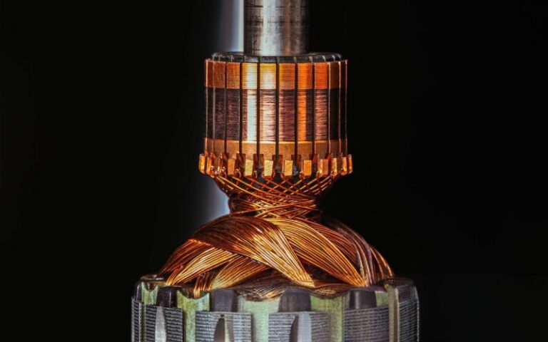
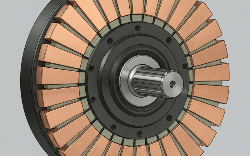
Design texts usually summarise commutator construction quickly: hard-drawn copper bars, trapezoidal in cross-section, insulated from each other by mica or micanite sheets, often around 0.8 mm thick, with the commutator diameter set to some fraction of armature diameter. It sounds clean and neat. Reality is a bit messier.
The copper bars want to move. At speed they try to climb outward, twist, tilt under electromagnetic torque, and bed in under the brushes. The mica segments stop them from touching each other electrically, but they also act as tiny structural columns between the bars and the hub, sharing some of the radial load. The lower the compressibility of the mica, the less the bar pack relaxes over time; too stiff and brittle, though, and you invite cracking during pressing, seasoning, or later commutator resurfacing.
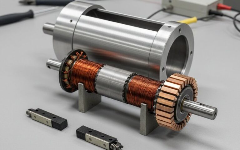
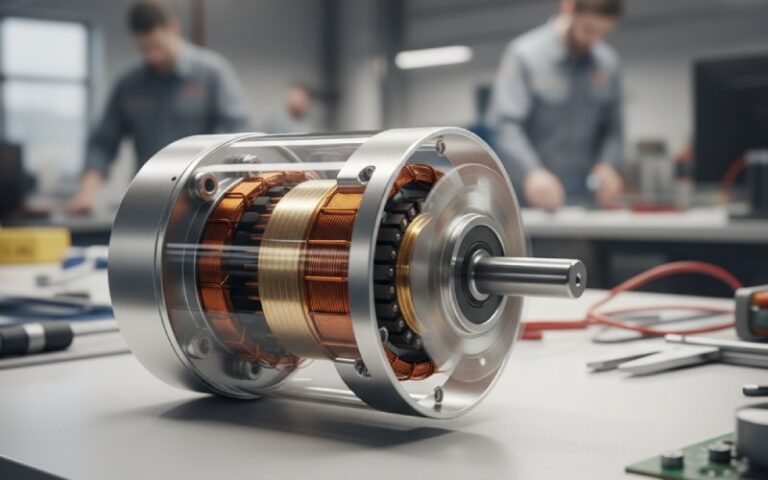
On modern semi-plastic commutators, the mica is often part of a composite: plastic shell forming the body, copper segments inserted, mica sheets between segments and toward the shaft, plus a metal bushing. The plastic deals with molding and weight, the copper carries current, and the mica quietly ensures that none of the bars think about shorting together under heat and pressure.
From a geometry point of view, the thickness of segment mica and its tolerance affect at least three things directly. First, bar pitch: the thicker the mica, the wider the commutator for the same number of segments, which feeds into brush width and armature design. Second, out-of-round growth: compressibility and creep of the mica decide how the cylinder behaves after seasoning and years of thermal cycling. Third, undercut strategy: how far below the bar surface you can safely groove the mica without running into weak, flaky material.
Undercutting: mica, brushes, and the depth that actually works
Mica is tough stuff. That is good for insulation life, but less nice for carbon brushes. If the mica stayed level with the bars, it would stand up to wear better than the copper. Over time the insulation would start to protrude, brushes would bounce, and commutation would degrade. This is why post-turning undercutting exists: you deliberately groove the insulation so its surface sits below the copper.
Service guides and repair shops treat undercutting almost as routine hygiene. The slits between segments are cut through the mica, micarta, resin or whatever insulation is used, to keep the brush track clear and limit rubbing of the brush on the insulation.citeturn9view0 If this is neglected, you start to see arcing rings around the commutator, vibration symptoms, accelerated brush wear, and sometimes the tell-tale dark streaks of carbon tracking across the mica.
The details that separate a good undercut from a mediocre one are rarely in the official docs. Depth proportional to bar pitch, chamfered edges so the brushes see a gentle step instead of a sharp edge, clean slots without conductive dust, and verification that the mica you are cutting into is not de-bonded underneath. Segment mica that chips instead of forming clean grooves is already telling you about its internal condition.
Thermal and dielectric expectations
High-heat, high-voltage mica laminates used for commutator insulation routinely offer breakdown strengths above 20 kV/mm, with operating temperatures reaching several hundred degrees Celsius depending on mica type and binder system. Muscovite-based materials tend to prioritise dielectric strength and stability, while phlogopite versions tolerate higher temperatures at the cost of some electrical margin.
For most DC motors and generators, the working stresses are far below these catalog numbers. Creepage distances, pollution degree, and contamination from brush dust will set your functional limit sooner than intrinsic mica breakdown. What matters more in everyday service is voltage endurance under partial discharge, arc erosion resistance around the brush track, and how the insulation behaves after thousands of warm-up and cool-down cycles.
Low moisture absorption is another quiet requirement. Many commutator-grade mica plates are formulated to minimise water uptake and preserve insulation resistance even in humid environments. If you have ever megger-tested a motor after a rainy shutdown and seen commutator resistance sitting suspiciously low, you already know why dry storage and bake-out matter as much as material datasheets.
Manufacturing realities that matter more than the brochure
The theory says: choose the right NEMA grade, press the segment stack, season, machine, undercut. The practice adds a long list of small knobs that quietly determine whether that same commutator is still running smoothly fifteen years later.
Pressing pressure and temperature profile need to match the specific mica plate and binder system. Too cold or too gentle, and you get residual voids and incomplete cure at the interfaces. Too aggressive, and you crush the mica, thin the insulation where you least want it, or trigger microcracks that only show up when the machine is spun close to overspeed. Technical notes on commutator mica emphasise multi-hour curing at elevated temperature precisely to avoid later “oozing” or binder migration.
Punching or machining the segment mica from sheet stock introduces its own issues. Punch too dull, and edges fray; frayed edges become stress risers when you press the stack and later when you turn and undercut. Saw cut too fast and you overheat the binder locally; that spot may shrink differently during seasoning, nudging one bar proud of its neighbours.
Seasoning and spin-testing also tie back into mica behaviour. Large machines and high-risk applications often specify overspeed spin conditioning or special seasoning cycles to prove that individual segments, the mica wedges, and the hub stay locked together under centrifugal load. If the mica formulation is marginal, this is typically where segment creep or wedge protrusion appears.
Failure signatures that trace back to segment mica
Field failures rarely show up as “mica problem” on the work order. They arrive as brush sparking, commutator bar discoloration, unexplained vibration, or nuisance trips. Yet several well-known patterns point back to segment insulation.
One and two-pole sparking around the commutator can be triggered by weak or damaged mica between segments, rough commutator surfaces, or out-of-round conditions. If the mica has cracked, loosened, or receded unevenly, the brush sees variable impedance and step changes along the track, and commutation goes ragged even with good brush pressure and alignment.
Carbon tracking across mica is another symptom. Insulation that has been contaminated with conductive dust or oil may form paths that partially bypass the mica. At first that just shows as local heating and a faint ring. Given enough time, it can evolve into bar-to-bar shorting around the periphery.
At the more mechanical end, segment “wobble” or breathing under load often indicates that the mica and copper stack have lost their original fit. Maybe the mica compressed gradually under centrifugal force, or perhaps it was over-machined during a previous resurfacing. Either way, once relative motion starts, you get fretting, loosened wedges, and eventually bars that move enough to chew brushes or crack the undercut corners.
Specifying segment mica with real constraints in mind
Most spec sheets already tell you dielectric strength, thickness range, binder content, and temperature class. In practice, what you want to write into your requirements often looks more like this, even if you do not phrase it that way.
You want a mica grade whose compressibility and strength keep the commutator round at your maximum peripheral speed and overspeed test, with a margin for re-turning over the life of the machine. You want a binder system fully cured at the manufacturer, with published data on long-term thermal shrinkage so you do not discover bar loosening after a few years of cycling. You want thickness tolerances tight enough that stack-up across hundreds of segments stays within your allowed bar height spread, otherwise you spend that tolerance later in machining.
Then you match temperature class and dielectric margin to your insulation system and duty. For a small tool motor with a molded commutator shell, plastic plus thin mica or even non-mica insulation may be fine, as long as the undercut process is controlled. For a large DC drive, traction motor, or high-speed generator, natural mica with shellac, alkyd-vinyl, or epoxy binder, NEMA-grade plates, and documented compressive and dielectric performance remain a sensible default.
Finally, you close the loop with machining requirements: specified undercut depth relative to bar pitch, surface finish range on the brush track, maximum allowed mica protrusion after service, and acceptable repair procedures for chipped or damaged segments. That is where the choice of mica and its machinability really show up on the shop floor.
Closing thought
Commutator segment mica does not draw much attention when a motor is running well. It just sits between copper bars, doing nothing visible. Yet it quietly establishes the mechanical stiffness of the commutator, the long-term stability of the brush track, and the insulation margin between segments and the hub. Get those few millimetres of material right, and the rest of the DC machine usually has a much easier life.