How to Determine the Number of Commutator Segments in a DC Motor
If the segment count is wrong, the problem usually does not start in the drawing. It starts later. The replacement commutator arrives, the armature does not match, the workshop stops, and someone has to explain why a simple count turned into rework.
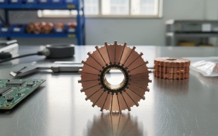
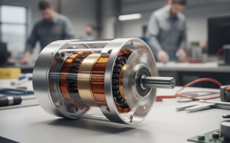
In our factory, we do not begin with the copper bars. We begin with the winding.
The rule is simple enough:
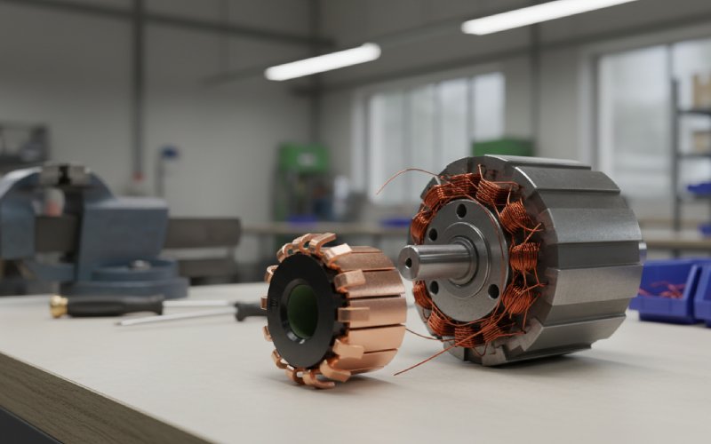
The number of active commutator segments equals the number of active armature coils.
That is the rule that matters. Everything else is a shortcut, and shortcuts need conditions.
Table of Contents
The fast rule most buyers use
For a standard double-layer DC armature with one coil side per slot per layer, the count is usually:
Commutator segments = slots
That is why a 24-slot armature often needs 24 segments. A 36-slot armature often needs 36 segments. Often. Not always.
This is where mistakes start. People remember the shortcut and forget the condition attached to it.
The calculation paths we actually use
1. When you know the slot count
Use this only when the armature is a normal double-layer winding and each slot layer carries one coil side.
Segments = Slots
This is the quickest method for standard production motors, service replacements, and many repeat OEM designs.
2. When you know the conductor data
If the armature drawing shows total active conductors and turns per coil, use the coil count directly:
Number of coils = Z / (2T)
Where:
- Z = total active armature conductors
- T = turns per coil
Then:
Number of commutator segments = Number of active coils
Example
If:
- total active conductors = 672
- turns per coil = 8
Then:
Coils = 672 / (2 × 8) = 42
So the armature needs:
42 commutator segments
No guessing. No slot-based shortcut.
3. When the slot does not carry only one coil side per layer
This is the case that gets misquoted in emails and RFQs.
If there are m coil sides per slot per layer, then:
Number of coils = m × S
Where:
- m = coil sides per slot per layer
- S = number of slots
And again:
Segments = Active coils
So if a winding layout creates more than one active coil per slot progression, slot count alone is not enough. A 24-slot armature does not automatically mean a 24-segment commutator. We see that mistake too often on rebuild jobs.
Do lap and wave winding change the segment count?
Not in the lazy way people assume.
Lap and wave winding mainly change the connection pattern, the parallel paths, and the commutator pitch. They do not cancel the core rule that active coils determine active segments.
A quick way to keep it straight:
- In simplex lap winding, the coil ends connect to adjacent commutator segments
- In simplex wave winding, the commutator pitch is roughly two pole pitches
- In both cases, you still count active coils first
So no, you do not calculate segment count from pole number alone. And no, brush count does not give you the answer either.
When “segments = slots” fails
There are three common reasons.
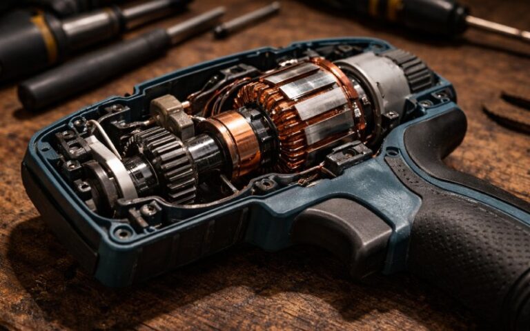
Dummy coils
Some wave-wound armatures cannot close electrically with the available slot combination. In that case, one surplus coil may remain in the slots for mechanical balance but stay electrically inactive.
It is physically there. It is not active. Do not count it as an active segment driver.
Dummy commutator segments
A surplus segment can sometimes be tied with an adjacent segment and treated as one effective segment in the winding scheme.
Again, the hardware count and the active electrical count stop matching one-to-one.
Nonstandard winding layout
Once the armature is no longer the usual double-layer, one-coil-side-per-layer arrangement, slot count becomes a rough clue, not a release number.
At that point we always go back to the winding data.
A practical table for segment count decisions
| What you have | What we check first | Working rule | Safe to quote immediately? |
|---|---|---|---|
| Slot count only | Whether it is a standard double-layer winding | Segments = Slots | Yes, if winding layout is confirmed |
| Total conductors + turns per coil | Active coil count | Segments = Z / (2T) | Yes |
| Slot count + coil sides per slot per layer | Coil density in the slot | Segments = m × S | Yes |
| Old sample only | Winding type, coil terminations, active layout | Count active coils, not just visible copper pieces | No, needs engineering check |
| Wave winding with closure issue | Whether dummy coil or dummy segment exists | Count active elements only | No, never quote from slot count alone |
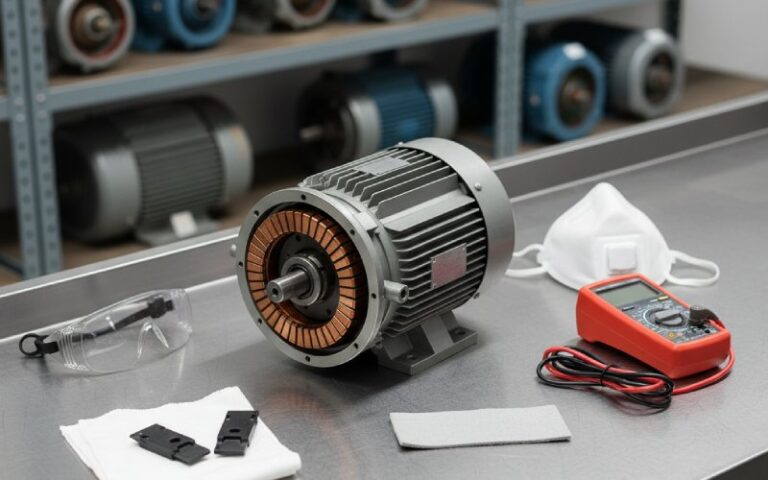
The design check people skip
A segment count can be mathematically correct and still be bad for manufacturing.
That part matters.
If the segment count is too low, voltage between adjacent segments rises and commutation becomes less forgiving. If the segment count is too high, segment pitch gets too small and the commutator becomes mechanically weaker.
In our design reviews, we do not stop at coil count. We also check whether the segment arrangement stays within practical commutator limits for pitch and inter-segment voltage. That is especially important in higher-speed DC motors and rebuild cases where the original design data is incomplete.
Why this matters to purchasing, not only engineering
Procurement teams usually do not care whether the winding is lap or wave. Fair enough. What they care about is whether the ordered part fits, ships on time, and avoids scrap.
A wrong segment count creates three direct risks:
- the commutator does not match the armature winding
- the replacement job stalls and lead time stretches
- the part may need rework or full replacement
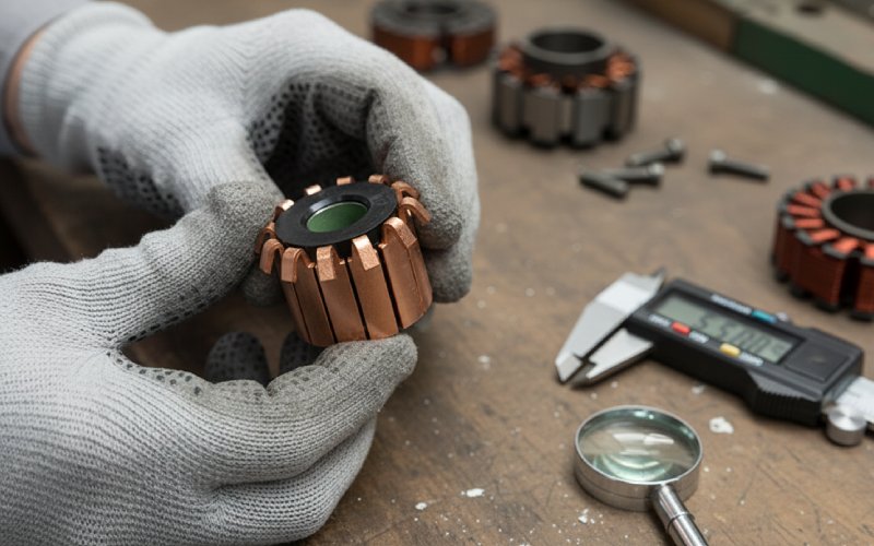
That is why we always ask for winding data, armature slot data, or sample photos before freezing the segment count on a custom order. The count looks simple. The cost of getting it wrong is not.
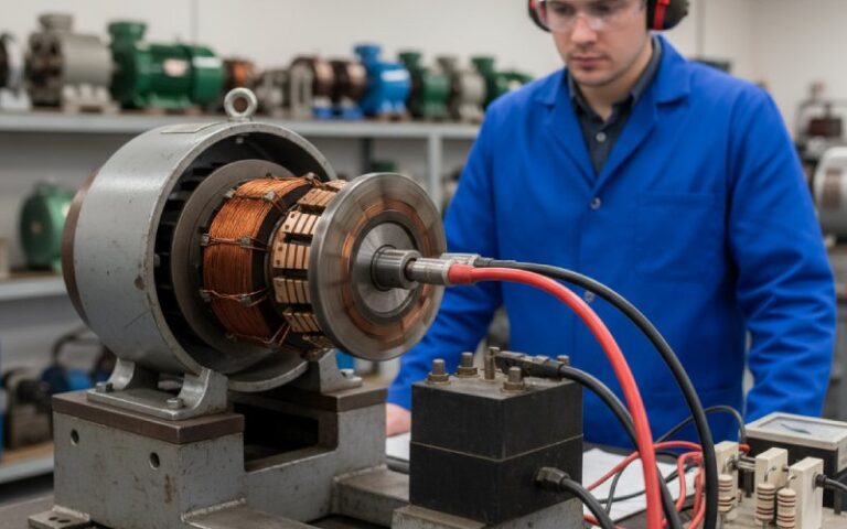
How we verify segment count before production
When customers send a new inquiry, we usually confirm the segment count in this order:
If you have a drawing
We check:
- armature slot count
- winding type
- turns per coil
- total active conductors
- whether any dummy coil arrangement exists
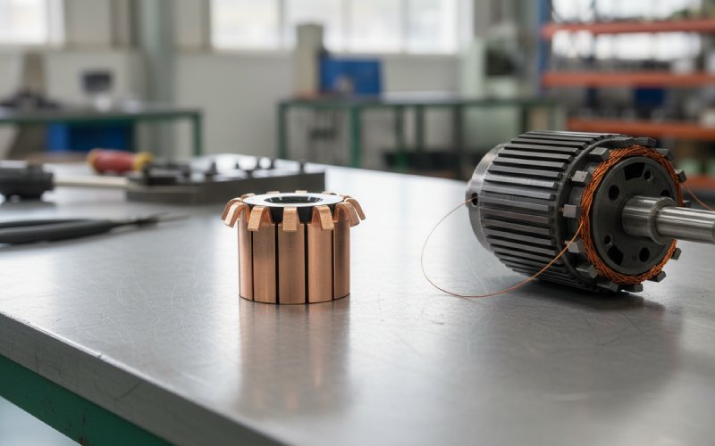
If you have only an old sample
We check:
- visible segment count
- riser connection pattern
- slot layout
- signs of dummy treatment
- whether the old commutator was original or already replaced once
That last point matters more than people think. A replacement part found in the field is not always a reliable baseline.
Common mistakes that keep showing up
Mistake 1: Counting poles instead of coils
Pole count affects the winding layout. It does not directly tell you the number of commutator segments.
Mistake 2: Assuming slots always equal segments
Only safe for the common double-layer case with the expected slot occupancy.
Mistake 3: Ignoring dummy coils in wave winding
This is a classic rebuild error. The armature looks complete. Electrically, one coil may not be part of the active circuit.
Mistake 4: Quoting from an old sample without checking the winding
We have seen field replacements where the visible part count was copied forward even though the previous repair had already introduced a mismatch.
A quick selection guide
If you need a short answer during quotation, use this sequence:
- Count active coils
- Confirm winding type
- Check whether slots really map one-to-one to coils
- Check for dummy coil or dummy segment
- Release segment count only after that
If all conditions are standard, the answer often collapses to one line:
For a standard double-layer DC armature, the number of commutator segments is usually equal to the number of slots.
But “usually” is doing work there. Do not ignore it.
FAQ
Are commutator segments always equal to the number of slots in a DC motor?
No. They are equal to the number of active armature coils. In a standard double-layer armature, that often becomes segments = slots. Outside that layout, the shortcut can fail.
How do I calculate commutator segments from winding data?
Use:
Segments = Z / (2T)
Where Z is total active conductors and T is turns per coil. That gives the active coil count, which gives the active segment count.
Does the number of poles determine the number of commutator segments?
No. Pole number affects winding arrangement and parallel paths. It does not directly define segment count.
Does lap winding use a different segment count from wave winding?
Not by default. What changes is the connection scheme and commutator pitch. In both cases, the segment count still follows the number of active coils.
Can a DC motor have a dummy coil and still look complete?
Yes. A dummy coil can stay in the slots for balance while being electrically inactive. That is why visual counting alone is not always enough.
What is the safest way to confirm segment count for a replacement commutator?
Use the armature drawing if available. If not, verify the winding pattern, conductor data, slot arrangement, and existing commutator connections together. Counting bars alone is not a reliable engineering method for every motor.
Final check before you place an order
If the armature is standard, the segment count may be easy. If the armature is old, repaired, wave-wound, or undocumented, it is not.
That difference decides whether the replacement part fits on the first run.
If you are not fully sure about your commutator segment count, send us your drawing, winding data, or clear photos of the armature and old commutator. Our engineering team will check the segment count before quotation and help you avoid a wrong build.