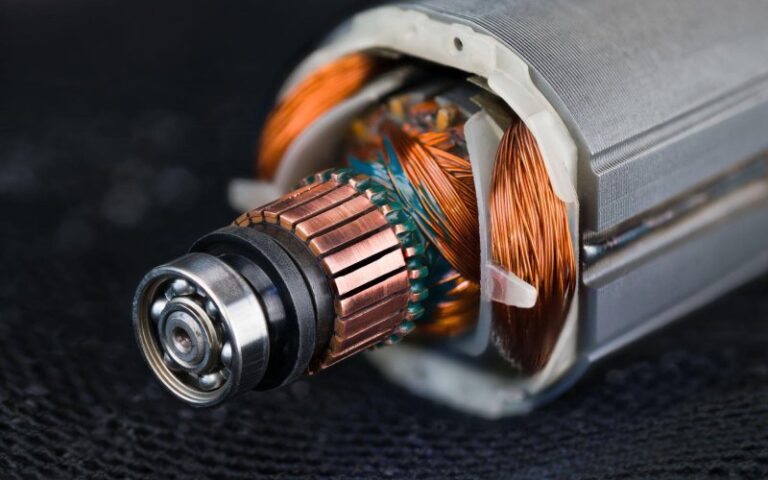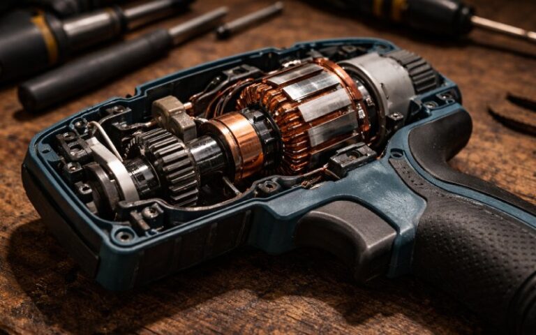
How Commutator Profiling Improves Motor Reliability in Production
A commutator rarely fails in a dramatic way first. Usually it starts smaller than that.
A little more brush dust than expected.
A track that looks slightly uneven.
Sparking that should have stayed under control, but did not.
Then the blame moves around. Brush grade. Spring pressure. Assembly. Operating current. Sometimes those are the cause. Often they are just where the symptoms show up.
In our factory, commutator profiling sits earlier in the chain.
We do not use it as a showroom term. We use it because dimensional compliance on a drawing is not the same thing as stable contact in a running motor. A commutator can pass size inspection and still create trouble later if the profile is unstable, if segment height drifts, if runout opens up under assembly stress, if one local area behaves differently from the rest. That is where field complaints begin. Quietly.
So when people ask why commutator profiling matters for motor performance, our answer is simple: it matters because motor performance starts to degrade at the contact surface long before the full failure is obvious.
Table of Contents
Why We Profile Commutators During Production
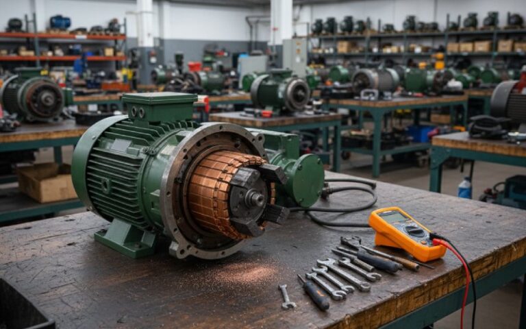
For a manufacturer, profiling is not about explaining what went wrong after the motor comes back. It is about stopping repeatable defects before shipment.
That changes the whole role of the measurement.
We use profile data to verify:
- running surface consistency
- bar-to-bar height control
- local high or low segment behavior
- roundness stability after machining
- batch repeatability from one production lot to the next
This is not a paperwork exercise. If the contact surface is inconsistent, the brush does not ride evenly. Then contact pressure shifts. Current distribution shifts. Heat shifts. Wear becomes selective. After that, even a well-designed motor starts losing margin.
Not because the commutator looked bad. Because it was not stable enough.
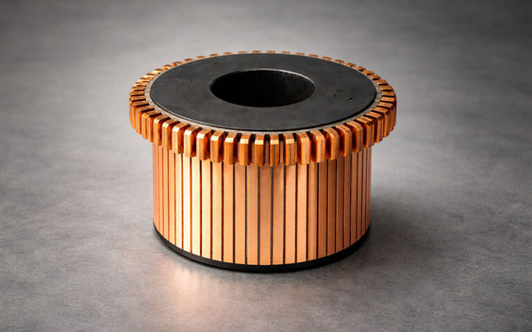
What We Actually Look For
We are not trying to collect more numbers than necessary. We are trying to separate harmless variation from variation that will show up in the field.
The first checkpoints are usually these:
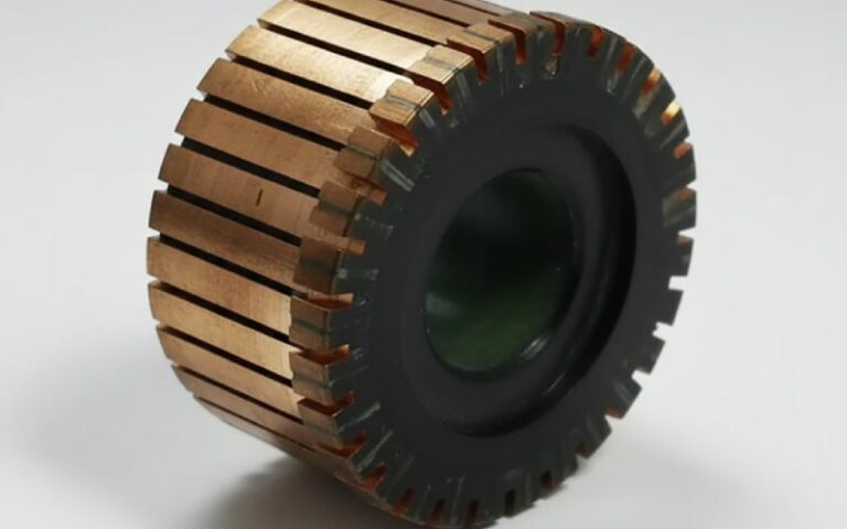
1. Runout
Overall runout tells us whether the commutator surface is staying true through machining and assembly. When runout is not controlled, brush contact becomes uneven over the rotation cycle. The motor may still run. It just stops running cleanly.
2. Bar-to-Bar Variation
This is one of the most useful indicators in production. A commutator can look acceptable as a whole and still have segment-to-segment inconsistency that disturbs brush travel. That kind of defect tends to repeat itself. Same position. Same wear signature. Same complaint, later.
3. Local High Bars or Low Bars
A single local deviation can do more damage than a broad but smaller variation. One unstable segment is enough to create a repeating disturbance in service. Especially in higher-speed or higher-duty applications.
4. Roundness After Machining
A turned surface is not automatically a stable surface. Tool condition, setup control, copper behavior, assembly compression, all of that leaves a pattern. Sometimes the pattern is small. Small is still enough.
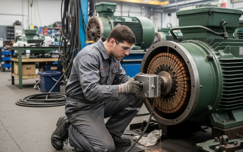
5. Batch Consistency
This matters for OEM buyers more than for anyone else. One good sample proves very little. What matters is whether the same profile quality is held across the batch, then across the next batch, then the next. That is where supplier capability starts to show.
The Real Link Between Profiling and Motor Performance
The link is not abstract.
If the commutator surface is inconsistent, the brush cannot maintain uniform contact. If contact is not uniform, the electrical path does not stay uniform either. The result may show up as:
- unstable commutation
- uneven brush wear
- local heating
- copper drag
- faster track deterioration
- more rework during assembly or testing
- earlier field complaints
Engineers already know this in fragments. Brush issue here. Sparking there. Wear pattern somewhere else. Profiling connects those fragments back to the same surface.
That is why we do not treat profiling as a maintenance-only method. It is a manufacturing control method. Better to catch the geometry before it becomes a warranty discussion.
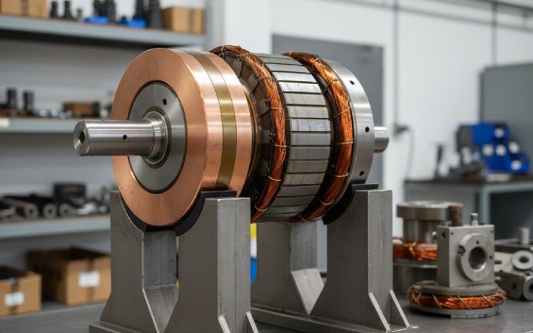
What Profiling Changes in Commutator Manufacturing
It changes decisions.
Without profiling, a supplier may rely too heavily on diameter checks, visual finish, or sampling logic that misses local defects. With profiling, the conversation gets stricter. A lot more specific.
We can see whether:
- the segment pack remained stable after assembly
- machining is producing uniform results or printing a repeat pattern
- a process drift started before it becomes visible to the operator
- one batch behaves differently from the last
- a returned part shows production deviation or service-side damage
That last point matters. Not every damaged commutator was made badly. Not every returned part failed in the field for the same reason either. Profile data helps us separate production issues from operating issues, which is useful for both supplier control and customer-side analysis.
How Profiling Supports OEM Buyers
From the buyer side, the question is not “Does the supplier own measuring equipment?”
The better question is: Can the supplier use profile data to reduce variation in shipped parts?
That is the commercial value.
A buyer does not benefit from inspection alone. A buyer benefits when inspection feeds back into the process — tool correction, setup correction, assembly correction, tighter release criteria, more stable batches.
Here is how we frame it internally:
| Profiling checkpoint | What it tells us in production | What it means for the customer |
|---|---|---|
| Overall runout | Whether the running surface stays true after assembly and machining | Lower risk of unstable brush contact and cyclic vibration effects |
| Bar-to-bar variation | Whether segment height remains consistent across the circumference | Lower risk of selective brush wear and localized sparking |
| Local profile deviation | Whether one segment or one area is outside stable behavior | Lower risk of repeating field defects tied to one angular position |
| Roundness trend | Whether machining quality is actually uniform, not just visually acceptable | Better commutation stability and less corrective work during motor assembly |
| Batch-to-batch profile repeatability | Whether process control is stable over time | More predictable quality in serial production |
This is the part many product pages skip. Buyers are not only buying copper, insulation, and dimensions. They are buying control. They are buying less variation.

Where Supplier Evaluation Usually Goes Wrong
A lot of sourcing decisions still lean too much on drawings, price, and sample approval.
That is not enough.
A commutator supplier should be able to discuss:
- how runout is controlled during production
- how bar-to-bar variation is checked
- what happens when local segment deviation is found
- whether profiling is tied to release criteria
- how results are tracked across batches
- whether sample reports can be provided for technical review
If the supplier cannot explain that clearly, then the quality system may be more visual than analytical. That works until the application gets demanding. Then it stops working.
Why This Matters More in Precision or Demanding Applications
Some motors tolerate inconsistency better than others. Some do not.
In applications with higher speeds, repeated start-stop cycles, tighter brush behavior requirements, or stricter life expectations, small profile errors become visible sooner. Not always during incoming inspection. Sometimes only after assembly. Sometimes only after runtime.
That is why we put more weight on profile stability when producing commutators for:
- precision DC motor applications
- higher-duty industrial motors
- applications with strict brush wear expectations
- designs where field maintenance is expensive or disruptive
The cost of weak profile control is usually not the rejected part itself. It is the downstream cost. Assembly time. Troubleshooting time. Return analysis. Replacement cycles. Lost confidence in the supplier.
Our Practical Rule
If a defect repeats, the geometry usually leaves a pattern.
That rule is not perfect. Still useful.
A once-per-revolution symptom points us in one direction.
A once-per-segment disturbance points somewhere else.
A broad unstable track suggests something else again.
That is how profiling earns its place in manufacturing. Not as theory. As a faster route to the root cause.
What OEM and Purchasing Teams Should Ask a Commutator Supplier
If you are comparing suppliers, ask for more than a dimension sheet.
Ask these instead:
- Do you control bar-to-bar variation during production, or only check final dimensions?
- Can you provide commutator profile data for sample approval?
- How do you handle local segment deviation when the part is otherwise within drawing size?
- Is profiling part of batch release for critical designs?
- Can your engineering team review our motor application and recommend tighter profile-related controls where needed?
Those questions usually separate a machining vendor from a manufacturing partner.
FAQ
What is a commutator profiler in manufacturing use?
In manufacturing, a commutator profiler is used to verify the actual running surface of the commutator, not just its nominal size. We use it to control runout, segment consistency, local profile deviation, and process repeatability before shipment.
Why does commutator profiling matter if the drawing dimensions are already correct?
Because drawing dimensions do not always show how stable the contact surface will be in operation. A part can be within size tolerance and still create brush instability if profile-related variation is not controlled.
Is profiling only necessary for high-end motors?
No. It becomes more critical as duty and performance requirements rise, but even standard motor programs benefit from better surface consistency. The difference is usually seen in brush behavior, assembly stability, and lower field variation.
Can profiling reduce motor sparking?
It can reduce one major cause of sparking: unstable mechanical contact at the commutator surface. Sparking is not caused by one factor only, but poor profile control is a common contributor and should not be ignored.
What should a buyer request from a commutator supplier?
At minimum: profile-related quality information, control methods for runout and bar-to-bar variation, and sample inspection data for technical review. For critical designs, batch-level consistency matters more than one approved sample.
Do you provide profile-based quality support for custom projects?
Yes. For custom commutator projects, our engineering team reviews drawing requirements, application conditions, and profile-sensitive risk points before production. That helps reduce avoidable issues later in assembly and service.
Need a Sample Profile Report for Your Design?
If your motor program has strict requirements on brush life, sparking control, or batch consistency, send us your drawing or sample. Our engineering team can review the profile-sensitive points and provide manufacturing feedback before production starts.