Commutator Pitch: The Deep, Intuitive Guide (With Real Design Insight)
Most explanations of commutator pitch are just one-line definitions and a formula. Useful? Kind of. Memorable? Not really.
Here we’ll treat commutator pitch the way a good designer or exam-taker actually thinks about it: as the link between slots, coils, commutator segments, and the voltage/current rating of a DC machine. The goal is that, by the end, you can feel when a value of (Yc) is right or wrong—without staring at the formula for five minutes.
Table of Contents
In one minute: what “commutator pitch” really is
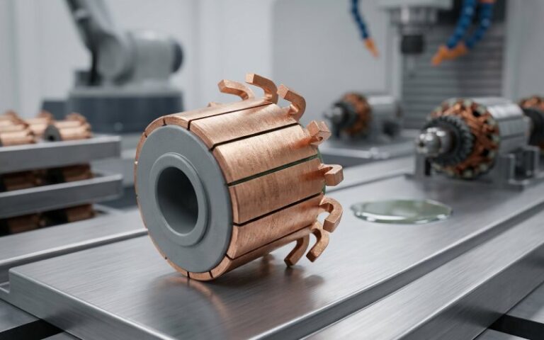
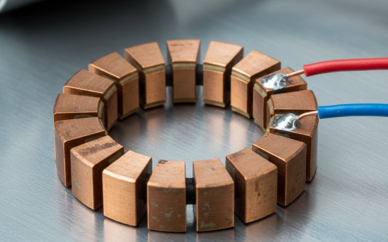
- Definition (core idea): Commutator pitch (Yc) is the number of commutator segments between the two segments to which the ends of a single armature coil are connected. It’s measured in “segments”, not in millimetres.
- Physical picture: Take any coil in the armature. Follow one end to a commutator segment. Walk around the commutator to the other end’s segment. The “step” you just took, counted in segments, is the commutator pitch.
- Why it matters: That step size decides whether the winding is lap or wave, sets how many parallel paths you get, and therefore whether your machine is naturally a high-current/low-voltage beast or a low-current/high-voltage one.
- Rule of thumb:
- Simplex lap winding → (Yc=±1) (coil ends on adjacent segments)
- Simplex wave winding → (Yc) is roughly two pole pitches in terms of commutator segments (a big leap around the commutator).
- Simplex lap winding → (Yc=±1) (coil ends on adjacent segments)
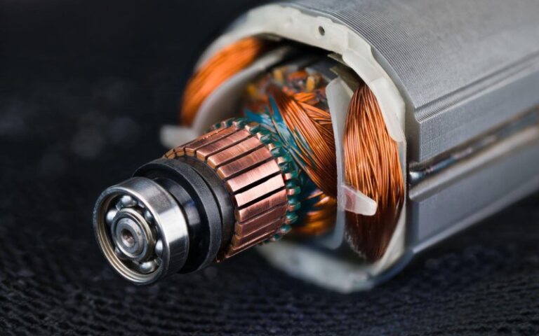
Zooming out: armature, slots, coils and where pitch fits
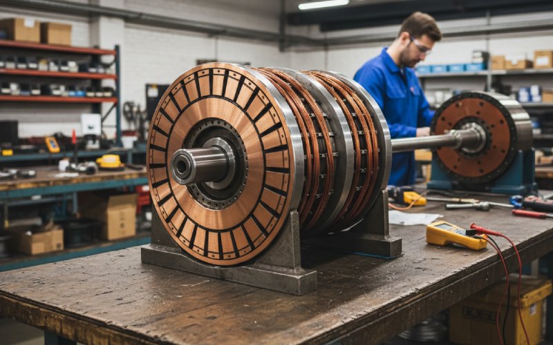
Inside a DC machine, the armature isn’t magic—it’s just a carefully organised mess of copper. You have slots in the iron, coil sides sitting in those slots, and a commutator that “samples” those coils. To get a sane winding, all the different “pitches” must cooperate: the slots must line up with poles, and the commutator segments must line up with coil connections in a way that closes on itself neatly.
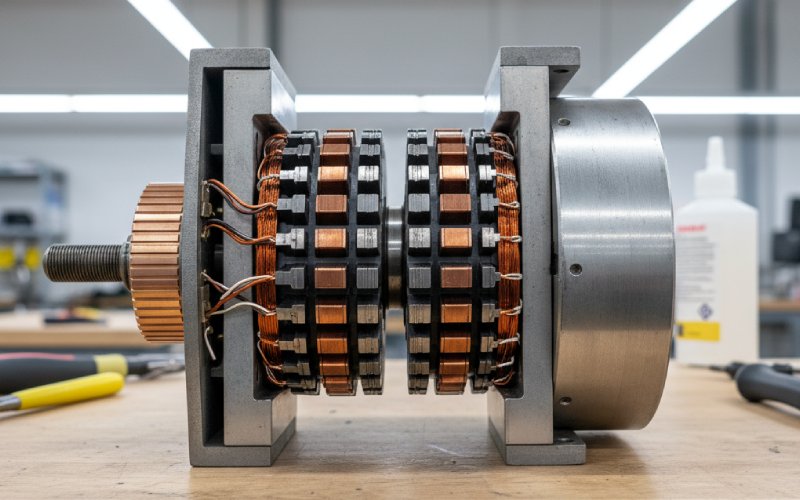
For a typical double-layer winding, there are two coil sides per slot; one is “top”, one is “bottom”. The distance between the sides of a given coil—the coil span—is usually chosen to be roughly equal to the pole pitch, i.e. number of slots per pole, so that each side of the coil sits under opposite magnetic poles and the induced EMFs add instead of cancelling.
All the pitch terms in one place (without the jargon pain)
- Pole pitch
Distance between two adjacent poles, expressed in slots or conductors. In slots,
Pole pitch≈S/P
where (S) = number of slots, (P) = number of poles. - Coil pitch / coil span (Ys)
Slot distance between the two sides of one coil. A full-pitch coil has coil pitch ≈ pole pitch; a fractional-pitch coil has a smaller span to help reduce certain harmonics. - Back pitch (Yb)
Distance (in conductors or slots) between the first and last conductors of a coil, measured on the back of the armature (the non-commutator end). It’s essentially the same as coil span. - Front pitch (Yf)
Distance between the second conductor of one coil and the first conductor of the next coil, measured at the commutator end of the armature (the “front”). These two coil sides are connected to the same commutator segment. - Resultant pitch (Yr)
Distance between the beginning of one coil and the beginning of the next coil to which it is connected. It’s more of a bookkeeping quantity when drawing winding diagrams. - Commutator pitch (Yc)
- Measured in commutator segments, not slots.
- For lap winding: (Yc = Yb – Yf).
- For wave winding: (Yc = Yb + Yf).
- Measured in commutator segments, not slots.
The formal definition (with formulas, but friendly)
At the pure textbook level, commutator pitch is:
“The number of commutator segments between the segments to which the two ends of a coil are connected.”
In a double-layer armature with (S) slots and (P) poles:
- Coil span is usually
Ys≈P/S
ensuring ~180° electrical separation between the two sides of a coil. - Each slot houses two sides from two different coils, so the number of coils equals the number of slots; the number of commutator segments is also equal to the number of coils.
With that in mind:
- Simplex lap winding
- The ends of a coil go to consecutive commutator segments.
- Mathematically:
Yc=+1(Progressive Lap)Yc=−1(Retrogressive Lap) - This is not an approximation; for simplex lap, (Yc=±1) always.
- The ends of a coil go to consecutive commutator segments.
- Simplex wave winding (double-layer)
- Coil ends land on segments roughly two pole pitches apart in terms of segments.
- In formula form:
Yc =2S/P±1
where (S) = slots (≈ commutator segments). - The exact sign (+/-) gives progressive or retrogressive wave winding.
- Coil ends land on segments roughly two pole pitches apart in terms of segments.
- In many design notes you’ll also see wave-winding formulas written as
Yc=P/2C±1
which is the same idea expressed using commutator bars directly.
The big takeaway: lap = tiny commutator step (±1), wave = big step (≈ two pole pitches) that makes the conductors “wave” under successive pole pairs.
Worked example: calculating (Yc) step-by-step
- Step 1 – Choose a simple machine
Say we have a 4-pole DC machine with 24 slots, double-layer winding. So:- (P = 4), (S = 24)
- Number of coils = 24
- Number of commutator segments = 24 (one per coil).
- (P = 4), (S = 24)
- Step 2 – Coil span / pole pitch
Pole pitch in slots:
Pole pitch = S/P = 24/4 = 6 slots
For a full-pitch coil, (Ys = 6) slots. So if one side is in slot 1 (top), the other is in slot 7 (bottom). - Step 3 – Simplex lap winding: find (Yc)
- By definition of simplex lap,
Yc = +1 (progressive) - Coil (1–7′) might connect to commutator bars 1 and 2.
- The next coil in sequence connects 2–3, then 3–4, and so on: the winding laps back under each pole, giving multiple parallel paths.
- By definition of simplex lap,
- Step 4 – Simplex wave winding: find (Yc)
- Use the formula:
Yc = 2S/P +/- 1 = (2 * 24)/4 +/- 1 = 12 +/- 1 - So (Yc = 11) (progressive) or (13) (retrogressive). Both are integers, so both are valid candidates.
- If we pick (Yc = 11), it means each coil’s second end is 11 segments away from its first, around the commutator. Tracing the connection around the armature, you’ll see the winding “waves” through all pole pairs before closing.
- Use the formula:
- Step 5 – Sanity checks
- (Yc) is an integer — always required, since you can’t connect to “half a segment”.
- The winding closes on itself after visiting all coils exactly once (no separate loops). If it doesn’t, your chosen (Yc) is wrong or incompatible with (S) and (P).
- (Yc) is an integer — always required, since you can’t connect to “half a segment”.
How commutator pitch shapes lap vs wave windings
The reason teachers obsess over commutator pitch is that it quietly controls the electrical personality of the machine. A small pitch (lap) produces many parallel paths; a large pitch (wave) makes only two paths that snake through all poles. This directly affects voltage and current capability, and therefore where each winding type is used.
Here’s a compact comparison you can keep handy:
| Aspect | Lap winding | Wave winding |
| Typical commutator pitch (Yc) | ( ± 1) (adjacent segments) | (2S/P ± 1) or (bars ± 1) / pole pairs (≈ two pole pitches) |
| Number of parallel paths (A) | (A = P) (equal to number of poles) | (A = 2) (independent of poles) |
| Voltage / current tendency | Lower voltage, higher current (many parallel paths) | Higher voltage, lower current (few parallel paths) |
| Typical applications | Low-voltage, heavy-current machines (e.g., electro-plating sets, welding generators) | Higher-voltage DC generators/motors where current is moderate |
| Visual feel of winding | Coils “lap” back under the next pole; paths are short | Coils “wave” from one pole pair to the next before returning |
Once you see this table, (Yc) stops being a random number and becomes a design knob: change (Yc), and you change the whole character of the armature.
Rules of thumb when choosing or checking commutator pitch
- Keep coils full-pitched unless you deliberately want fractional pitch
Back and front pitches are usually chosen close to the pole pitch so the coil sees maximum flux; fractional pitches are used mainly for harmonic control. - For simplex lap, don’t “invent” Yc values
If a problem or design says “simplex lap winding”, the correct answer for commutator pitch is always (+1) or (-1). Anything else means you’re not looking at a simplex lap any more. - For simplex wave, think “two pole pitches” and then fix the arithmetic
Start with (Yc ≈ 2S/P). Adjust with ±1 until you get an integer that actually works in your winding diagram. - Make sure (Yc) is an integer and gives a closed winding
Because (Yc) counts segments, fractional values are impossible in practice; if simple algebra gives you 11.5, it’s a sign that your chosen number of slots or poles is incompatible with that type of wave winding. - Remember the plex
In multiplex lap windings, (Yc) equals the “plex” (1 for simplex, 2 for duplex, etc.), so larger (Yc) means more parallel paths in lap windings as well.
How commutator pitch shows up in performance and testing
When you look at real DC machines, commutator pitch pops up in places that don’t explicitly say “pitch” in the spec sheet. The number of parallel paths (A) in the armature, which depends on winding type (and therefore (Yc)), appears directly in the classic EMF equation:
E = (PZ / 2A) φ ω_m
where (P) = poles, (Z) = total conductors, (φ) = flux per pole, (ω_m) = mechanical speed.
A lap-wound machine (with (A = P)) naturally produces lower voltage but higher current capability than a wave-wound machine with the same (P, Z, φ, ω_m) but (A = 2). That’s not a coincidence; it’s the direct consequence of commutator pitch choosing how conductors are grouped into paths.
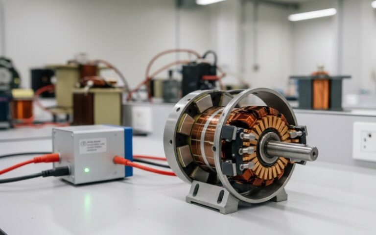
So when you’re working in a lab and see a big chunky DC generator with thick armature leads and relatively low terminal voltage, there’s a good chance its (Yc) quietly told the designer, “make me lap-wound.”
Troubleshooting & “gut feel” for bad commutator pitch
- Winding won’t close properly
If you start from one coil and, following the connection rule implied by your (Yc), either skip some coils or come back early to the start, your chosen commutator pitch is incompatible with (S) and (P). - Unequal brush currents on an otherwise symmetrical machine
For a machine that should be perfectly symmetrical, weird brush currents can be a sign of incorrect connections—often traceable to a wrong hop count in the commutator (i.e., wrong (Yc)). - Persistent sparking even after brush seating and cleaning
If the brushes are properly set on the commutating plane and the commutator surface is good, but sparking remains, mis-connected coils or broken equaliser connections (again tied to how coils land on segments) are suspects. - “Dead spots” in a reconstructed or rewound armature
If someone has rewound a motor and chosen an incorrect step around the commutator, the rotor can land in positions where no effective torque is produced—a practical symptom of a wrong commutator pitch pattern.
Wrapping up: how to own commutator pitch
If you remember only three things from this:
- Concept – Commutator pitch (Yc) is simply “how many commutator segments apart the two ends of a coil are.”
- Lap vs wave – Lap: (Yc = ± 1), many parallel paths. Wave: (Yc ≈ 2S/P), always two parallel paths.
- Design mindset – Once you pick machine type → winding type → (Yc), you’ve committed to a certain voltage/current personality. Everything else (slots, bars, pitch corrections) is about making that choice physically consistent.