Commutator Parts: Anatomy, Materials & A Practical Guide to Getting Them Right
In the world of DC motors and generators, commutators are the unsung heroes that quietly make everything work… right up until they don’t. When a commutator fails, it usually isn’t “the commutator” in the abstract – it’s a very specific part of it: a cracked bar, carbonized mica, loose riser, warped shell, or chewed-up brush track. Understanding those parts is the difference between guessing at failures and actually controlling them.
- In this guide, you’ll see:
- What each commutator part actually does in real life, not just in textbooks
- The main materials behind those parts (copper, mica, plastics, steel, etc.) and why they’re used
- How different commutator designs (slot, tang, semi-plastic, molded) change the parts you buy
- Typical failure patterns and what they say about the underlying parts
- A practical checklist for specifying replacement commutators or individual parts
- What each commutator part actually does in real life, not just in textbooks
Table of Contents
Where Commutator Parts Show Up in the Real World
If your day job involves traction drives, cranes, hoists, winders, power tools, blowers, or any older plant with DC machines, you’re living with commutator parts whether you think about them or not. DC “commutator machines” are still common in traction, automotive auxiliaries, industrial drives and small appliances, even as brushless motors spread.
- Typical places you’ll find commutators and their parts:
- Large DC motors in mills, mines, and rolling stock
- Starter motors and auxiliary motors in vehicles
- Universal motors in drills, grinders, vacuum cleaners
- DC generators and older power / excitation systems
- Tiny brushed DC motors in toys, fans, pumps, and actuators
- Large DC motors in mills, mines, and rolling stock
The Basic Idea: What a Commutator Is
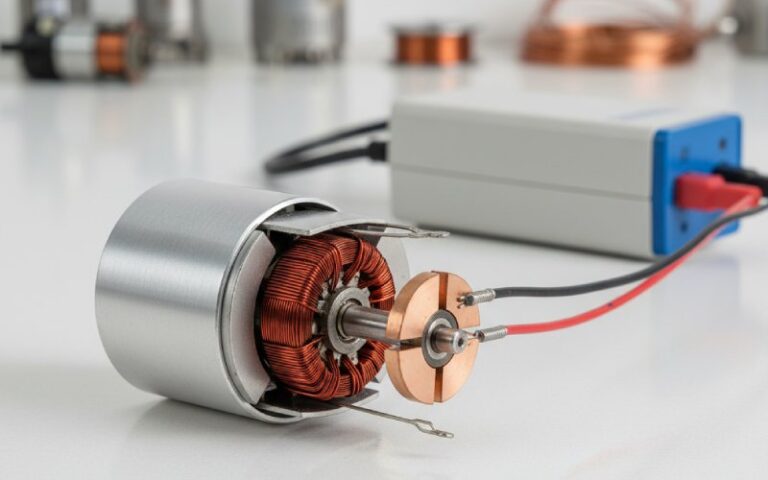
At its core, a commutator is a rotary electrical switch built onto the rotor (armature). As the rotor spins, the commutator reverses the direction of current in specific coils at exactly the right moments, so the torque on the shaft keeps pushing in the same direction. In generators, it takes an AC-like voltage from the armature and “mechanically rectifies” it into a DC output.
- In plain language:
- The armature windings are where energy is converted.
- The commutator parts are the hardware that make those windings usable: they connect, switch, insulate, and survive mechanical abuse and heat.
- The brushes are just the sliding interface between your external circuit and that rotating copper-and-mica stack.
- The armature windings are where energy is converted.
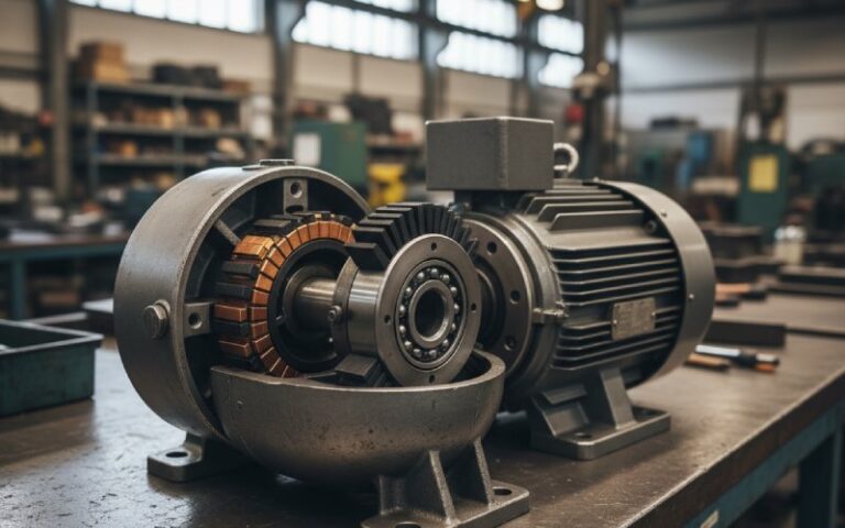
Anatomy of a Commutator: The Main Parts
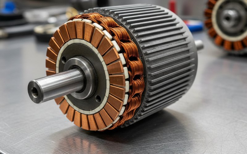
If you slice a commutator open, you don’t just see “copper and mica.” You see a carefully layered structure, each part with a specific job and failure mode. Classic bar-type commutators for DC motors are typically built from:
- Key commutator parts (bar-type / industrial-style):
- Copper segments (bars) – hard-drawn copper “wedges” arranged around the shaft; one per coil or coil group
- Inter-segment insulation (segment mica / separator mica) – thin mica strips between bars, keeping them electrically isolated
- Shell / hub / body – steel or iron structure that carries mechanical loads and supports the bar stack
- V-rings / end insulation – molded or machined mica (or other insulation) rings at the ends of the segment stack
- Risers / tangs / hooks – the connection feature that accepts the armature winding (slot-type riser, or hook/tang-type connection)
- Bore / bush / keyway – inner portion that fits onto the shaft, often with a metal bushing
- Bands / shrink rings / glass bindings – external bands that clamp the assembly and provide mechanical strength, especially on large machines
- Copper segments (bars) – hard-drawn copper “wedges” arranged around the shaft; one per coil or coil group
Quick Reference: Commutator Parts, Materials & Failure Signals
Here’s a compact table you can use when you’re staring at a motor on the shop floor and trying to decode what went wrong.
| Commutator Part | Typical Material(s) | Primary Role | Common Problems You’ll See |
| Copper segments (bars) | Hard-drawn Cu, often with 0.03–0.1% Ag for strength | Conduct current between brush and coil; brush track | Pitting, ridging, bar burning, bar-to-bar shorts, lifted bars |
| Segment insulation (mica) | Natural / built-up mica, mica paper composites | Insulate bars from each other and from the body | High mica, carbonization, tracking, lifted/missing mica |
| V-rings / end insulation | Molded mica rings or mica composites | Axial insulation and mechanical clamping of the stack | Cracking, loose rings, contamination paths |
| Shell / hub / body | Steel or iron, sometimes cast | Carry mechanical stresses, support segments | Out-of-round, cracked hub, fretting on shaft |
| Risers / tangs / hooks | Copper, integral with bars or attached | Connection point for coil ends | Loose connections, cracked tangs, solder failures |
| Bands / shrink rings | Forged steel rings, glass-fiber bands, epoxy | Hold the outer diameter under compression | Band cracking, loosening, corrosion |
| Bush / bore / keyway | Steel or bronze bushing, machined bore | Fit the commutator securely to the shaft | Wear, misfit, shaft damage |
| Plastic shell (semi-plastic types) | High-temp engineering plastics + copper bars | Integrate segments + insulation for small DC motors | Cracked plastic, thermal deformation, tracking |
How These Parts Work Together in Operation
In service, every commutator part is juggling more than one job: carrying current, dissipating heat, resisting centrifugal force, and coping with constant brush contact and arcing. Copper segments see enormous numbers of make/break events as they pass under the brushes, while the mica insulation holds the whole system electrically together at high voltages and temperatures.
- Main stresses that drive commutator part design:
- Electrical: switching surges during commutation, arcing at the brush edge, bar-to-bar voltage, insulation aging
- Thermal: copper heating from current, local hot spots at poor connections, frictional heating at the brush face
- Mechanical: centrifugal forces on bars and bands, vibration, shock loading in traction or heavy machinery
- Chemical & environmental: oil mist, dust, conductive contamination, humidity, corrosive atmospheres
- Electrical: switching surges during commutation, arcing at the brush edge, bar-to-bar voltage, insulation aging
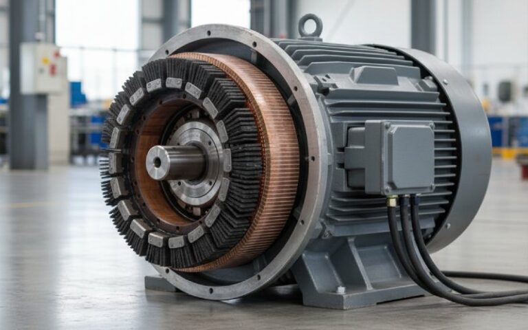
Different Commutator Designs = Different Parts
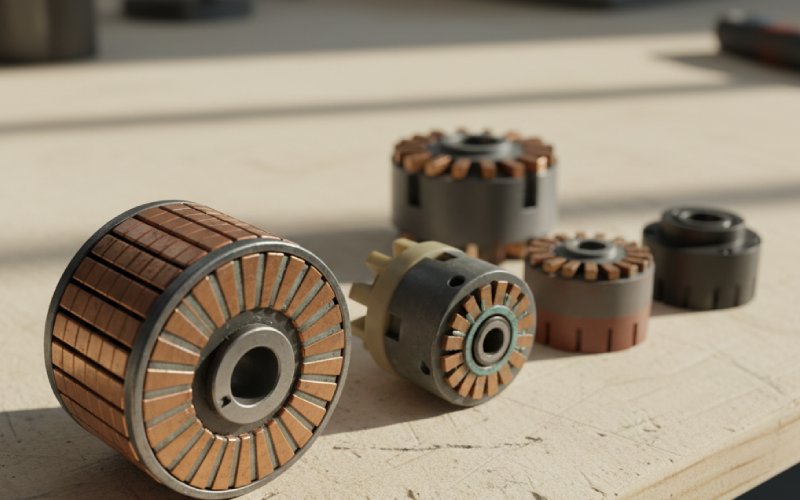
The phrase “commutator parts” covers a family of designs that share the same job but use different geometry and materials.
Traditional bar-type commutators on larger DC machines look like a stack of copper wedges with mica between them, clamped onto a steel body with bands and V-rings. Small motors and power tools increasingly use semi-plastic or molded commutators where a plastic shell, copper segments, and mica or resin insulation are molded into a compact unit.
- Common commutator types and what changes in their parts:
- Conventional / slot (bar) commutators – windings terminate in slots at the back of each bar; very robust for high vibration and high torque applications
- Tang / hook commutators – each bar has a “hook” that catches the magnet wire during automatic winding; fewer manual steps and lower cost but different failure patterns at the tang area
- Segmented commutators with steel hub – heavy-duty industrial units with silver-bearing copper bars, mica separators, V-rings, and shrink rings or glass bands for strength
- Semi-plastic / molded commutators – plastic shell plus copper bars and mica-like insulation, common in small DC and universal motors; very compact, often non-repairable and fully replaced when damaged
- Conventional / slot (bar) commutators – windings terminate in slots at the back of each bar; very robust for high vibration and high torque applications
Materials Deep Dive: Why Copper, Why Mica, Why Plastics?
If you look at serious commutator manufacturers, you’ll see a strong pattern: hard-drawn copper (sometimes with a splash of silver), mica-based insulation, and steel or plastic support structure. That’s not tradition; it’s physics and reliability.
- Practical material logic behind commutator parts:
- Copper (often Ag-bearing):
- High conductivity → lower losses and less heating
- Good mechanical strength when hard-drawn → resists centrifugal forces
- A touch of silver improves hot strength and fatigue resistance for heavy-duty traction and industrial motors
- High conductivity → lower losses and less heating
- Mica (segment mica, V-rings, built-up plates):
- Excellent dielectric strength and tracking resistance at high temperature
- Holds up under press-and-bake manufacturing processes
- Stays stable under mechanical pressure, making it ideal between copper bars and at V-rings
- Excellent dielectric strength and tracking resistance at high temperature
- Plastics (semi-plastic commutators):
- Allow complex shapes and integrated features to be molded in one shot
- Good for compact, low- to medium-power motors where replacement is cheaper than rebuild
- Must be carefully chosen for thermal class and long-term tracking resistance
- Allow complex shapes and integrated features to be molded in one shot
- Steel / glass bands and rings:
- Take the centrifugal load off the copper bars
- Keep the commutator round and mechanically sound over millions of revolutions
- Take the centrifugal load off the copper bars
- Copper (often Ag-bearing):
Failure Patterns: What They Tell You About Specific Parts
When things go wrong, the commutator surface is your crime scene. Each visible symptom usually points back to a particular part not doing its job – or being asked to do more than it was designed for.
- Typical symptoms and the commutator parts to suspect:
- Heavy sparking / bar burning at one area:
- Check for high bars or low mica, loose risers/tangs on specific segments, poor brush grade or pressure
- Check for high bars or low mica, loose risers/tangs on specific segments, poor brush grade or pressure
- Uniform grooving or ridging on the brush track:
- Look at brush hardness vs. copper hardness, contamination, or out-of-round commutator and loose bands
- Look at brush hardness vs. copper hardness, contamination, or out-of-round commutator and loose bands
- Blackened, carbonized mica:
- Insulation is overloaded or contaminated; may need undercutting, cleaning, or full rebuild of segment insulation
- Insulation is overloaded or contaminated; may need undercutting, cleaning, or full rebuild of segment insulation
- Lifted bars / cracked shell:
- Mechanical overload, inadequate banding, or thermal cycling attacking the steel shell, bands, or plastic body
- Mechanical overload, inadequate banding, or thermal cycling attacking the steel shell, bands, or plastic body
- Random bar-to-bar shorts:
- Contaminated or damaged segment mica, copper burrs between bars, smear from severe overheating
- Contaminated or damaged segment mica, copper burrs between bars, smear from severe overheating
- Heavy sparking / bar burning at one area:
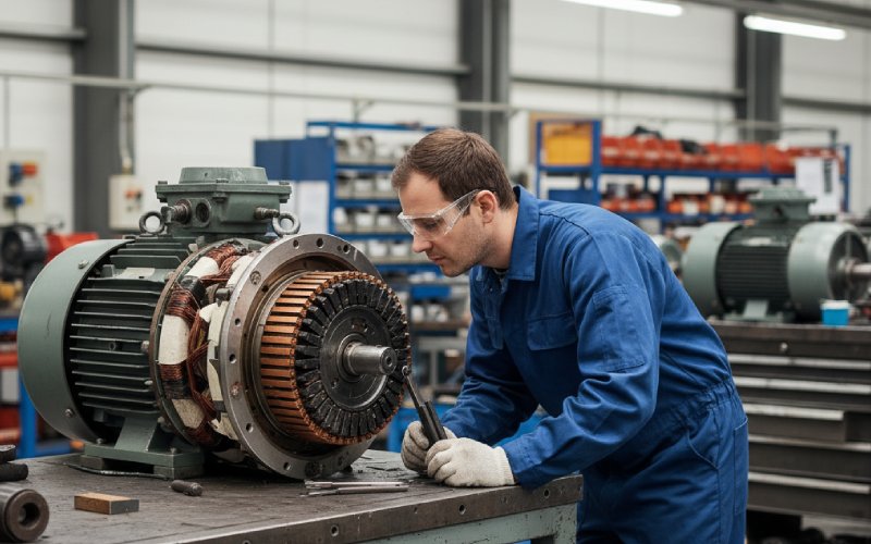
Inspection & Maintenance: Looking at the Parts, Not Just the Spark
Routine inspection is where you catch commutator-part issues while they’re still cheap. Instead of only asking “is it sparking?”, look at the parts themselves.
- A simple commutator-part inspection checklist:
- Visually scan the brush track – is the wear pattern even? Any local discoloration or bars that stand out?
- Check bar-to-bar insulation – look for mica that’s proud of the surface (“high mica”), cracks, or carbon tracking
- Measure commutator runout and roundness – excessive runout stresses bars, bands, and brushes
- Inspect risers / tangs / hook connections – any discoloration, loose coil ends, or signs of overheating at joints
- Look at bands / rings / shell – cracks, corrosion, looseness, or evidence of movement relative to the bars
- Listen and feel in operation – vibration, noise, and temperature rise often signal underlying mechanical issues with the body, bush, or bands
- Visually scan the brush track – is the wear pattern even? Any local discoloration or bars that stand out?
Specifying Replacement Commutators & Parts: A Buyer’s Checklist
When you’re ordering a replacement commutator or having one rebuilt, the quality of your specification directly determines the quality of what shows up. Modern suppliers typically ask for dimensions, bar count, application, and material preferences.
A bit of extra thought here can drastically extend motor life and reduce downtime.
- Key questions to answer before you send a RFQ:
- Dimensions: Outer diameter, inner diameter/bore, total height, copper height, and number of bars/segments
- Type: Conventional/slot vs. tang/hook, bar-type vs. semi-plastic/molded
- Application duty: Continuous vs. intermittent, starting duty, typical and peak current, speed range, vibration environment
- Environment: Temperature class, humidity, dust, oil mist, corrosives – all of which affect insulation choice
- Materials: Copper grade (with or without silver), preferred mica/insulation class, banding style (steel rings vs. glass)
- Repair philosophy: Do you want a fully repairable bar-type commutator, or is a molded disposable style acceptable for your process?
- Dimensions: Outer diameter, inner diameter/bore, total height, copper height, and number of bars/segments
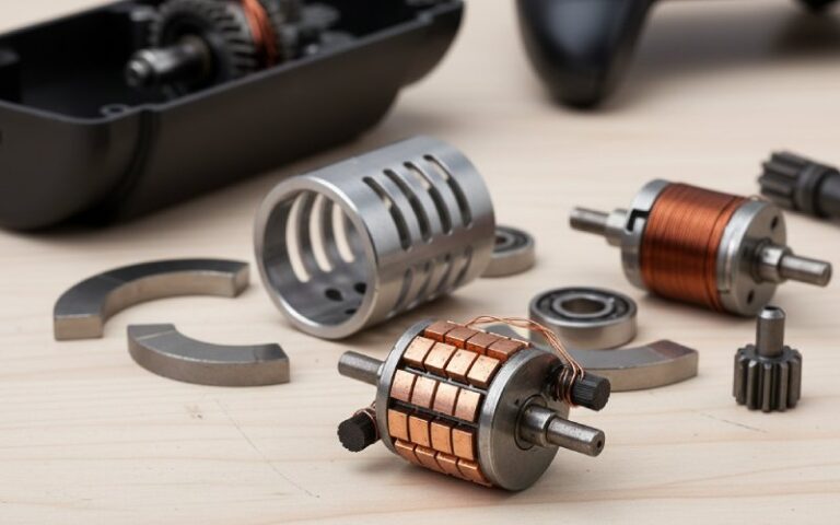
Semi-Plastic & Molded Commutators: When the Shell Is a Part
In many small motors – household appliances, automotive auxiliaries, consumer devices – the commutator is no longer a stack of separate copper bars and mica pieces on a steel hub. Instead, you’ll see a semi-plastic or molded design where a plastic shell carries the copper bars and mica or resin insulators in one compact unit.
- What changes for you when dealing with these designs:
- The plastic shell is now a critical structural and insulating part: it must tolerate heat from commutation and friction, and any cracks or carbon tracking usually mean full replacement.
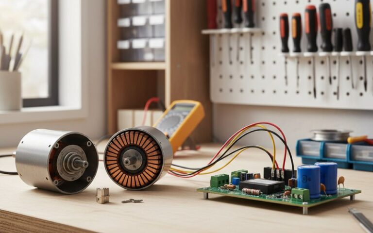
- Field repair options are limited: serious damage typically means swapping the entire rotor/armature instead of rebuilding a commutator stack.
- Correct thermal class and material selection at design time become even more important since you can’t easily “upgrade” later.
- The plastic shell is now a critical structural and insulating part: it must tolerate heat from commutation and friction, and any cracks or carbon tracking usually mean full replacement.
Looking Ahead: Are Commutator Parts Going Away?
Brushless DC motors and modern drives are absolutely eating into the territory of brushed DC machines. But as of today, huge numbers of existing assets – from traction drives and cranes to pumps, blowers, and power tools – still rely on commutators, and will do so for decades.
That means there’s real value in knowing your commutator parts at a deep, practical level:
- which part is failing,
- what that says about your application, and
- how smarter material and design choices can keep your machines running longer between teardowns.