Commutator Manufacturing Process: From Copper Segments to Finished Parts
The commutator manufacturing process usually includes copper strip preparation, segment blanking and forming, insulation molding, curing, bore and OD machining, mica undercutting, and final inspection. In our factory, that sequence is not treated as a row of separate operations. It is one system. If the early copper work drifts, the brush track tells on it later.
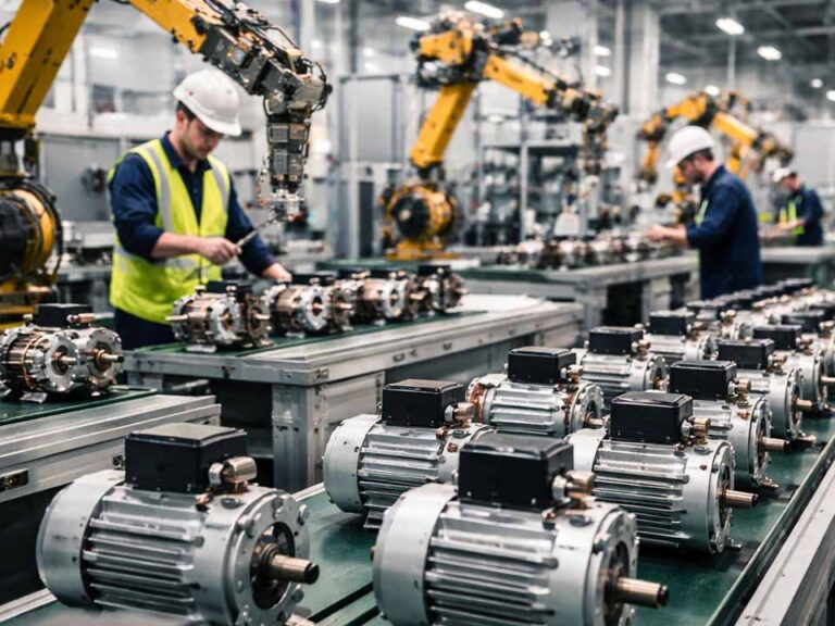
For buyers sourcing custom commutators for DC motors, universal motors, starter motors, and armature assemblies, the real question is not “what are the steps.” The real question is where the process usually goes unstable, and what a manufacturer actually controls before the part reaches your winding line or your motor assembly line.
We do not use machining to hide weak molding. We do not use inspection to excuse unstable segment forming. And we do not call a commutator finished because the copper surface looks clean in a tray.
Table of Contents
Copper Strip Selection for Commutator Segments
We start with copper behavior, not with finished dimensions.
Conductivity matters. So does formability. So does how the material behaves after stamping, after hook forming, after cure, after final turning. A copper strip that looks fine on the certificate can still create trouble in production if springback is inconsistent or if the edge condition changes too much from coil to coil.
That is why incoming material control is not limited to thickness and chemistry. We also watch forming response, burr tendency, and how stable the strip remains during repeated tool contact. A segment that fights the tool early usually causes more trouble later, not less.
For OEM commutator manufacturing, this part is easy to underestimate. Buyers often focus on outer diameter, segment count, or connection style first. Fair enough. But if the copper condition is wrong, the rest of the route becomes corrective work.
Commutator Segment Blanking and Forming
This is where hidden instability starts.
Blanking is not just about cutting the profile. We need stable width, repeatable edge quality, controlled burr direction, and predictable flatness. If burrs turn the wrong way, or the edge begins to tear instead of shear cleanly, later operations feel it. Slot cleaning gets worse. Bar-edge quality gets worse. Hook area consistency gets worse.
Then comes segment forming.
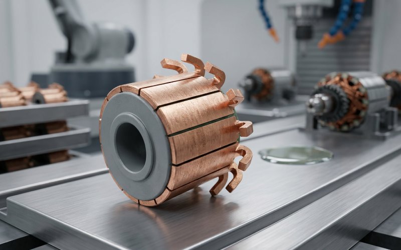
For hook-type and riser-type commutators, we form the connection features while the copper is still behaving in a controlled way. Not because that looks cleaner on a process chart. Because once the segment is assembled into the body, correction becomes slower and more expensive. Sometimes impossible.
Internal locking features matter here too. Tabs, tangs, undercuts, mechanical keys. Different designs use different geometry, but the point stays the same: the copper must stay locked when the rotor sees heat, speed, brush pressure, and vibration together. A segment that passes early inspection and shifts later is one of the more expensive defects in this business.
Commutator Insulation Molding and Segment Locking
Insulation is not a passive separator.
In a production commutator, insulation does three jobs at the same time. It prevents electrical shorting between segments. It holds segment position. It helps the whole body stay dimensionally calm during curing, machining, shaft fitting, and service.
That is why we do not treat insulation as filler.
Depending on the design, the build may use discrete insulation pieces, molded resin systems, or a combined locking structure that secures the copper bars into the body. What matters is not the brochure language around the material. What matters is whether the insulation system keeps the segment where it belongs when copper and resin want to move differently under heat.
Cleanliness also matters more than many people think. Small contamination in the cavity or between segment interfaces can show up later as false height variation, unstable seating, or local flash that gets mistaken for a machining problem. It was not a machining problem. It started earlier.
Curing and Structural Stabilization
A commutator body that is not fully settled will reveal that fact sooner or later.
Sometimes during boring. Sometimes during OD turning. Sometimes when the part is pressed onto the shaft. Sometimes only after the armature runs under load and temperature.
So curing is not just a time-and-temperature box to tick off. We look for real structural stability. Uneven shrinkage, trapped stress, segment movement during cure, weak support in the fixture, all of that feeds directly into runout, segment height spread, and press-fit consistency.
A rushed cure is one of those decisions that seems efficient for a few hours and then starts charging interest.
For custom armature commutators, this stage matters even more when the design uses thin segments, higher segment counts, or tighter fitting conditions. Small bodies do not forgive movement. Large bodies do not hide it.
Hook or Riser Forming and Armature Connection
The connection area deserves its own process window.
For hook commutators, wire insertion and forming force have to stay inside a narrow range. Too little control and the joint becomes unstable. Too much force and the copper cracks, the insulation gets damaged, or the geometry moves before finishing.
The same logic applies to riser designs. The connection must hold electrically and mechanically. Not in a sample. In volume.
When we evaluate this part of the route, we do not ask only whether the wire can be attached. We ask whether joint resistance stays consistent, whether the heat input remains controlled during fusing or welding, and whether the surrounding structure stays intact after the connection is made.
That matters in DC motor armatures, universal motor rotors, starter motor armatures, and high-cycle applications where local heating at one bad connection will not stay local for long.
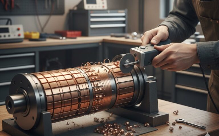
Commutator Machining: Bore, OD, and Face Turning
Machining should reveal geometry, not invent it.
We use finish machining to bring the commutator to final bore size, outer diameter, face condition, and concentricity. But machining is not where a weak process becomes a good process. It only exposes what the earlier stages already decided.
During bore machining, we care about size, roundness, surface condition, and fitting behavior. If the bore is unstable, shaft assembly becomes unstable. Too loose, and the commutator can move. Too tight, and something else starts yielding first.
During OD and face turning, copper behavior tells the truth fast. If the copper smears, if chips drag across the surface, if bar edges start rolling, if segment height varies too much after cleanup, we do not blame the tool first. We check the upstream process.
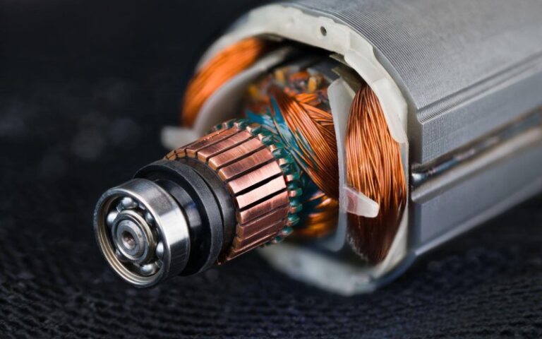
A good running surface is not mirror-polished. It is controlled. The brush track must establish cleanly and remain stable. Too rough is bad. Too smooth is also bad. A polished-looking surface is not automatically a better one.
Mica Undercutting and Bar Edge Chamfering
This stage is often described as finishing work. That is technically correct. It is also misleading.
Mica undercutting affects commutation behavior directly. If the insulation sits too high, the brush begins to ride the wrong geometry. If the slot is dirty, copper slivers remain in play. If the bar edges are left aggressive after undercutting, brush wear and sparking become easier to trigger.
So we check three things together:
- undercut depth
- slot cleanliness
- bar-edge condition
Not one by one. Together.
Bar-edge chamfering follows the same logic. A proper chamfer removes the sharp transition that can damage the brush path, but it must stay controlled. Too small and the edge remains risky. Too large and useful contact width is reduced for no good reason.
This is one of the most common reasons a commutator can look acceptable under simple visual inspection and still behave badly in service.
Final Inspection for Custom Commutators
Final inspection should follow failure mode, not just drawing tolerance.
We inspect dimensions, yes. OD, ID, length, segment count, pitch-related features where applicable. But production-grade inspection goes further than that. We also watch segment height relationship, runout, bore consistency, surface condition, insulation groove quality, and connection-zone stability.
For some projects, electrical checks matter just as much as dimensional checks. Segment-to-segment consistency tells you things that appearance cannot. So does mounting behavior. So does post-machining stability.
A finished commutator should do four things without argument:
- mount cleanly
- run true
- present a stable brush track
- keep segment behavior consistent across the full circumference
If it only looks good before assembly, it is not finished.
Process Control Table: Where Commutators Usually Go Wrong
| Process Stage | What We Control Hardest | Typical Failure Mode | What We Correct First |
|---|---|---|---|
| Copper strip preparation | Thickness stability, forming response, burr tendency | Inconsistent segment behavior across lots | Material window, incoming verification, strip condition |
| Segment blanking | Width, edge quality, burr direction, flatness | Torn edges, slot contamination, unstable bar edges | Tool wear limits, blanking clearance, edge review |
| Segment forming | Hook/riser geometry, locking feature repeatability | Cracked hooks, weak seating, shifted geometry | Forming load, copper hardness window, progressive die condition |
| Insulation molding | Segment position, cavity cleanliness, fill consistency | Height variation, flash, hidden movement after cure | Seating method, cavity cleaning, molding parameters |
| Curing | Time, temperature, fixture support, stress release | Runout drift, movement during boring or shaft fitting | Cure cycle, stabilization hold, fixture support |
| Bore and OD machining | Concentricity, chip control, surface condition | Smeared copper, rolled bar edges, unstable fit | Tool condition, cutting parameters, upstream trace-back |
| Mica undercutting | Depth, slot cleanliness, burr removal | High mica, brush chatter, sparking, edge burning | Recutting, cleaning, edge finishing |
| Final inspection | Runout, segment integrity, surface and electrical consistency | Field instability that was missed by simple visual checks | Root-cause review, not just sorting |
Seeing high mica, unstable brush tracks, or uneven segment wear on your current parts? Send us your drawing or failed samples for a technical review. We usually identify the process weak point faster when we can see both the part geometry and the service symptom together.
What Buyers Should Check Before Ordering a Custom Commutator
When buyers request a quotation, the drawing is only part of the story.
For a useful review, we usually need these details as well:
- motor type: DC motor, universal motor, starter motor, or other brushed design
- armature or rotor application
- connection style: hook, riser, slot, or other
- working speed and load
- current level or known heat issue
- shaft fitting method
- known field problem, if there is one
If the current issue is brush chatter, edge burning, unstable resistance, fit looseness, or segment lifting, say that early. Those symptoms narrow the manufacturing discussion quickly.
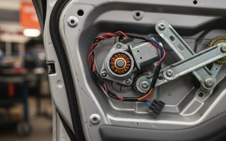
Why This Process Matters in DC Motor and Armature Applications
The commutator is small compared with the whole motor assembly. It still decides a lot.
In power tools, poor bar-edge condition can show up fast as brush noise or unstable wear. In starter motor commutators, joint stability and structural strength matter more because the load comes hard. In universal motor commutators, speed amplifies geometry mistakes. In armature repair and replacement projects, the buyer often inherits the defect history from the old design and needs a manufacturer who can read that history properly.
That is why we do not separate manufacturing from application. They are tied together whether the paperwork shows it or not.
FAQ: Commutator Manufacturing Process
What is the standard commutator manufacturing process?
A production commutator is typically made through copper strip preparation, segment blanking, segment forming, insulation molding or assembly, curing, bore and OD machining, mica undercutting, chamfering, and final inspection. The exact route changes with the design, but those are the control points most buyers should care about.
Why is segment forming so important in commutator production?
Because many later defects start there. Burr direction, hook shape, locking features, and forming stress all affect seating, molding stability, machining behavior, and final brush contact.
Why can a commutator pass inspection and still fail in service?
Because simple visual inspection does not reveal everything. Hidden stress in the body, unstable segment seating, local connection variation, poor slot cleanliness, or aggressive bar edges can survive a quick check and still create field problems later.
What causes high mica problems in a finished commutator?
Usually one of three things: undercut depth is wrong, the slot was not cleaned properly, or wear on the copper changed the relative height too quickly in service. High mica often shows up together with brush instability.
Is a smoother commutator surface always better?
No. A controlled running surface is better. Over-smoothed copper can be as troublesome as torn or rough copper. The goal is stable brush contact, not cosmetic shine.
What information should I send when asking for a custom commutator quote?
Send the drawing, motor type, armature application, segment count, connection style, operating conditions, and any known defect from your current part. If you have failed samples, send those too. They usually shorten the review cycle.
Discuss Your Custom Commutator Project With Us
If you are sourcing a custom commutator manufacturer for DC motors, universal motors, starter motors, or armature assemblies, send us your drawing, key dimensions, application details, and current failure mode.
We can review:
- new custom commutator designs
- replacement commutators for existing armatures
- hook and riser commutator projects
- commutator issues related to high mica, sparking, fit instability, or brush-track defects