Commutator End Frame: What Actually Fails And What Actually Matters
If the commutator is the brain of a brushed motor or starter, the commutator end frame is the neck you keep forgetting about until it gives out. It carries the bearing, fixes the brush position, routes the current, closes the magnetic and mechanical stack, and it usually gets blamed last. Treat it as a simple bracket and you end up debugging “mystery” brush wear and slow cranking for months. Treat it as a precision interface and the whole machine behaves.
Table of Contents
Where The Commutator End Frame Really Sits In The System
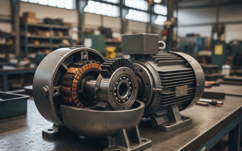
In a DC motor or automotive starter, the commutator side is already crowded: copper segments, carbon brushes, terminations, switching noise, and plenty of heat. The end frame or end bracket is the structural shell that holds all of that in a repeatable relationship to the rotor. It is the commutator side housing, carrying the bearing pocket, brush windows or holders, terminal hardware, and often the ground path.
Production catalogues treat it as a casting, a bracket, sometimes just a part number grouped with “engine-fuel components” for starters. But in practice it fixes three things you care about more than the marketing copy suggests. It defines the rotor-to-stator air gap at the commutator side. It defines where each brush actually lands on the commutator bars. And it defines how loads from the vehicle or driven machine get into your bearing. All three live inside one tolerance stack, exactly where this frame sits.
The moment you look at rebuild instructions for a commutator end frame terminal kit, the importance becomes obvious. You do not just “swap the housing”; you strip insulators, replace hardware in a certain order, and are told explicitly which surfaces must stay clean and insulated. Those are not legal instructions. They are hard-won lessons from field failures, encoded in service documents.
Design Choices That Quietly Control Your Motor
You already know the drawing symbols and insulation classes. The useful part is thinking about the frame as one place where mechanical, electrical, and manufacturing compromises collide. The names change with vendor and sector – end frame, end bracket, cover – but the questions you should ask stay similar.
Geometry, alignment and the commutating plane
The end frame fixes the brush ring position. That means it also fixes the effective commutating plane, together with any field distortion. If the frame is stamped or deep-drawn from sheet metal, as in some patented bracket designs, any warp or residual stress moves that plane.
Most teams obsess over the rotor shaft runout and forget that a slightly oval bearing bore in the end frame pushes the rotor off-centre on the commutator side. Now the air gap is tighter near one pole, the magnetic field distorts, and the neutral plane shifts. You then compensate by twisting brush holders or changing spring force. The origin looked mechanical, not electrical, but it is both.
On high-volume stamped brackets, window edges that hold brushes are another quiet alignment mechanism. If those edges carry burrs or spring-back, the brush holder may cock a degree or two. That small angle, at the commutator radius, is enough to skew wear patterns on the bars and lift the contact film.
Material and thermal behavior
Traditional end frames for larger machines lean toward cast iron or steel; smaller motors and starters often use cast or die-cast aluminium, sometimes with plastic or composite inserts for insulation and brush carriers. The trade-offs are predictable but easy to misjudge.
Stiffer metals keep the bearing alignment stable under external loads and temperature swings. Aluminium cuts mass and conducts heat away from the commutator zone, but the bearing pocket grows more with temperature and needs careful control of interference fit. Composite structures can integrate creepage distance and cable routing neatly but add complexity when you want to press in a metallic bearing seat.
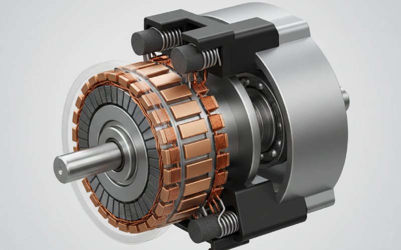
Thermal paths deserve more attention than they usually get. Heat from arcing at the brushes flows through the commutator, shaft, bearing, frame, then to the outer housing or gearbox. If the frame is thin and interrupted by large windows, your thermal path is chopped into small ribs. Short duty-cycle starters survive that easily. Continuous-duty DC machines do not forgive it.
Brushes, insulators and terminals
For many automotive starter end frames, the brush gear and terminal package are intrinsic parts of the assembly. Brass or copper studs run through the frame, insulated by moulded or fibre components; connections to the solenoid or battery cable sit right there.
The design game is to keep creepage and clearance distances clean while still giving a path for carbon dust to escape. Every sharp corner in a brush window collects dust, moisture, and oil vapour. Given enough starts, that becomes a conductive bridge along the frame. Engineers often compensate late in the project with exotic coatings. A simpler move earlier is to round or taper those pockets and give dust an escape path that does not cross high voltage gradients.
Terminal packaging is equally subtle. Short, direct studs reduce resistance and voltage drop, then surprise you with torque-induced stress on the insulators when a mechanic over-tightens a nut. Longer, more flexible studs relax the stress but increase inductance and exposure to vibration. Neither is wrong; one aligns better with your duty cycle and service culture.
Bearing support and lubrication path
The end frame bearing bore looks innocent on the drawing. In use, it sees misaligned belt tension, vehicle vibration, and the occasional crowbar during disassembly. If you are designing a new frame, consider the whole bearing stack: snap-ring grooves, thrust faces, grease pockets, and any shields that try to keep brush dust out of the bearing.
Cheap frames sometimes combine a relatively soft housing with a press-fit bearing that is just a little too tight in worst-case tolerance. After some thermal cycles the bore relaxes, the fit changes, and you get creeping or spinning of the outer race. The symptom is slow cranking, then a noisy bearing, then a scrapped starter that “just wore out early”. The root cause lives in that first choice of pocket tolerance and material.
Sealing and contamination
On paper, ingress protection is a couple of rating letters. On an actual starter mounted low in a vehicle, the commutator end frame is sprayed with water, salt, oil, and road grit every winter. The same windows that let brushes breathe also let droplets in.
Some designs accept that fate and rely on gravity and orientation to keep contamination below the brush zone. Others bring a simple rubber gasket between the frame and the next housing section, or build in a drain notch at the lowest edge. This is small geometry, but it decides whether carbon dust forms a paste and tracks along an insulator, or falls out harmlessly at the bottom.
Failure Modes You Actually See On The Bench
Textbooks love ideal commutation; the workshop table tells a different story. Here the end frame leaves its fingerprints on every failure, even when the commutator itself looks like the culprit.
Cracked frames come first. Impact or over-tightened mounting bolts create hairline cracks from bolt holes outward. On a bench test the motor might still spin; under real load the frame flexes, the bearing tilts, and the armature starts rubbing the stator or pole shoes. The complaint becomes “only fails hot” or “works out of the car, not in it”.
Next is bearing pocket wear. Once the bearing can move radially, the commutator wobbles. Brushes see changing contact pressure and arc more, which accelerates both brush and commutator wear. You can replace brushes three times and still miss the root cause because the frame bore looks fine until you measure it properly.
Then you have insulation issues. Carbon tracking between terminal studs and the metal body, or between brush holders and ground, shows up as faint grey trails and discoloured resin. It may only break down at higher voltage or under wet conditions, which makes diagnosis fun.
To make this less abstract, it helps to relate system-level symptoms back to what you can see on the end frame during inspection.
| Vehicle or system symptom | What you see on the commutator end frame | Likely mechanism inside the frame | Quick action that actually helps |
|---|---|---|---|
| Slow cranking or weak torque on a starter after a short life | Bearing pocket slightly oval, brush wear uneven around the circumference | Misaligned rotor and shifted neutral plane due to frame distortion or poor bearing fit | Measure bore, check frame flatness, replace frame instead of just brushes |
| Intermittent no-start, especially after rain or washing | Dark tracking paths between terminal hardware and metal body, damp carbon dust around brush windows | Surface leakage or partial discharge across contaminated insulators on or through the frame | Clean or replace insulators, consider geometry changes that let dust and water drain away |
| Excessive brush wear and noisy commutator on a DC motor | Brush holders slightly skewed in frame windows, spring angles inconsistent | Stamped or cast windows out of tolerance, causing brush misalignment and unstable film | Rework or redesign windows and carriers, not only brush grade |
| Motor passes factory test but fails early in field vibration | Fine cracks around mounting lugs or in thin ribs of end bracket | High cyclic stress in frame lugs, sometimes aggravated by casting defects from poor gating | Revisit casting quality and lug geometry; use simulation or gating redesign rather than just thicker ribs |
The pattern is that the frame rarely fails electrically by itself. It quietly shifts geometry until the electromagnetic design you signed off no longer exists in the running machine.
Manufacturing Reality: Casting, Stamping And What You Actually Receive
Many commutator end frames in volume production are cast aluminium or iron parts. Others are deep-drawn or stamped steel brackets with integrated windows and a drawn bearing cup. In both cases the finished part depends heavily on process decisions that often get treated as “supplier details”.
Casting work on brackets has shown repeated issues with incomplete fill, cold shuts, and porosity when gating is not tuned for these thin-walled geometries. Optimisation studies on commutator end brackets use simulation to balance fill time, temperature, and shrinkage so that critical features like bearing bosses and mounting ears stay sound. When that work is skipped, porosity lands exactly where you least want it: under the bearing seat or around the lugs.
Stamped brackets look safer until you track spring-back. After forming, the bearing cup and brush window walls relax slightly. The supplier may hit nominal dimensions in a static gauge but still deliver variability that lines up uncomfortably with your tolerances on rotor length and brush holder stack.
Coatings and surface treatments are another quiet variable. A frame that was drawn and dimensioned bare may ship e-coated or painted, shrinking clearances in windows and over-insulating surfaces you intended as clean ground paths. Again, the drawing may still be technically correct while the assembly performance drifts.
So, rather than only chasing Cpk on a few headline dimensions, it pays to ask three uglier questions early. First, which features are formed or machined last, after most stress is locked in. Second, how the supplier is controlling distortion from heat treatment or coating. Third, where porosity or thinning is most likely around bearing and mounting areas, based on the actual flow path or forming sequence rather than a tidy sketch.
Specifying And Sourcing A Commutator End Frame Assembly
In the automotive world you will often meet commutator end frames only as OE part numbers: small assemblies sold as complete housings with brush gear and terminals in place. Toyota’s starter “commutator end frame assemblies” are typical, advertised as key components in engine starting rather than as standalone motor parts.
When you are sourcing replacements or designing a drop-in equivalent, the numbering hides quite a lot. The practical path usually runs something like this, though not always in a straight line.
You start by freezing the interfaces. That means mounting pattern to the gearbox or engine, the fit to the next housing section, shaft size and bearing type, and brush-to-commutator geometry. The last of those is easiest to get wrong because you will often be reverse-engineering from a worn unit. Measuring brush track angle and overhang on a used commutator is noisy; a better approach is to measure from clean datum features on the frame to the commutator land itself, preferably across several samples.
Electrical interfaces come next. You want to know not just the stud thread and position, but the intended path from external cable lug through stud, into any copper bussing, then into the brush leads. Resistance targets are usually small but non-zero. If your substitute frame re-routes that path with a different stack of insulators or copper, you may have shifted voltage drop enough to matter for low-voltage cranking.
Insulation and creepage distances should respect the original machine’s working voltage plus whatever transients your system throws in. For 12 V or 24 V starters this often seems trivial, until you remember corrosive environments and conductive films. A modest increase in distance and a reduction in sharp corners where moisture can cling costs almost nothing at design time.
Finally comes serviceability. If your customer base is rebuilding these units, they care whether the frame assembly can be stripped and re-built without specialised fixtures. Documented instructions from major suppliers for commutator end frame terminal kits usually show a deliberate order for removing clips, screws, insulators, and housings. Matching or improving that ergonomics is part of the product, even if it never appears in the CAD model.
Using The End Frame As A Design Lever, Not Just A Line Item
Because the commutator end frame lives at the intersection of structure, insulation, and thermal management, it is one of the cheapest places to change the behaviour of a motor or starter without touching the electromagnetic design. Shift a bearing pocket, adjust window geometry, change material or thickness in a few ribs, and you can meaningfully alter vibration response, brush life, and contamination tolerance.
The habit in many teams is to lock in the frame early as a commodity component and spend the next year tuning brush grade, spring force, and control algorithms. A more productive loop is almost the reverse. Fix the electromagnetic design and brush geometry early based on solid references for commutation in DC machines. Then treat the end frame as a structural element that must keep that geometry intact under all realistic loads, contamination scenarios, and maintenance practices.
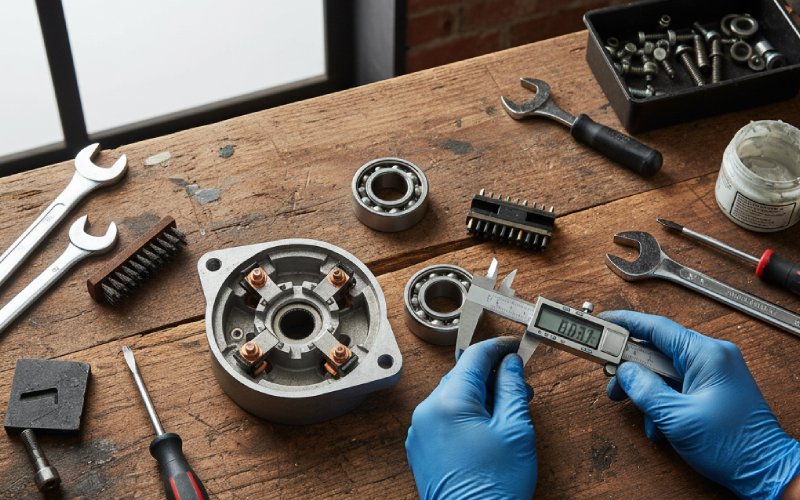
So next time you review a motor or starter that is “almost there”, resist the urge to only tweak brush data or control code. Take one quiet afternoon with a stripped unit, a height gauge, and a handful of used commutator end frames from the field. Measure what the machine has really become on its commutator side. Look at cracks around lugs and bearing pockets, at brush windows that show uneven polish, at tracks of carbon and moisture along insulators.
You may find that the real lever is not another exotic brush or another control tweak at all. It is a slightly smarter, sturdier commutator end frame that keeps the geometry you already designed, through the actual life your customer gives it.