Commutator Design for Manufacturing (DFM) & OEM Production
Turn your commutator drawing into stable production—without guesswork. XDC is an OEM commutator manufacturer focused on build-to-print manufacturing plus practical DFM feedback to prevent avoidable failures (runout, flashover, overheating, brush wear).
DFM review + quote within 12 hours (business days) after receiving drawings/specs
Build-to-print manufacturing for hook / slot / shell / planar commutator structures
Controlled machining: turning, mica undercutting, surface finish, dynamic balancing
Designed for your duty & environment: humidity, contaminants, altitude, thermal cycling
File types accepted: PDF, DWG, STEP, IGS, X_T, SolidWorks, ZIP
Clear Scope: DFM + Manufacturing, Not Motor R&D
XDC does not design complete motors from scratch. Our value is different: we take your commutator drawing/specification and make it manufacturable, repeatable, and inspection-ready—then produce prototypes and mass production with controlled processes.
What you get from us
DFM feedback tied to manufacturing realities (tolerances, tooling limits, stability at speed)
Material alignment (copper grade, insulation system, molding compounds)
Process planning (turning/undercutting/balancing/inspection checkpoints)
Factory-direct quotation and production schedule planning
DFM Review Deliverables
A quote without engineering review is a risk. Our DFM review focuses on the items that typically cause commutator failures in real machines.
Segment pitch & integrity: manufacturability and heat capacity (typical minimum pitch guideline ≥ 4 mm depending on structure)
Insulation system: interbar mica/micanite selection and thickness (typical processing range 0.6–1.5 mm, often ~0.8 mm interbar)
Voltage/current density sanity check: segment voltage guideline (~20 V/segment typical) and current density targets (up to 12–30 A/cm² for heavy-duty low-voltage systems)
Brush interface: brush grade match and commutating zone coverage (typical coverage ≤ 15% of circumference)
Runout & concentricity risks: features that drive sparking/uneven wear
Surface finish requirement: target Ra 0.4–0.8 µm for stable film formation
Speed & mechanical limits: peripheral speed targets (general-purpose ≤ 15 m/s; reinforced constructions for 65–90 m/s applications)
Balancing plan: dynamic balancing grades such as G2.5 / G1.0 when required
Environment notes: humidity/contaminants/altitude implications and mitigations
All values are typical manufacturing references. Final limits depend on your drawing, duty cycle, and operating environment.
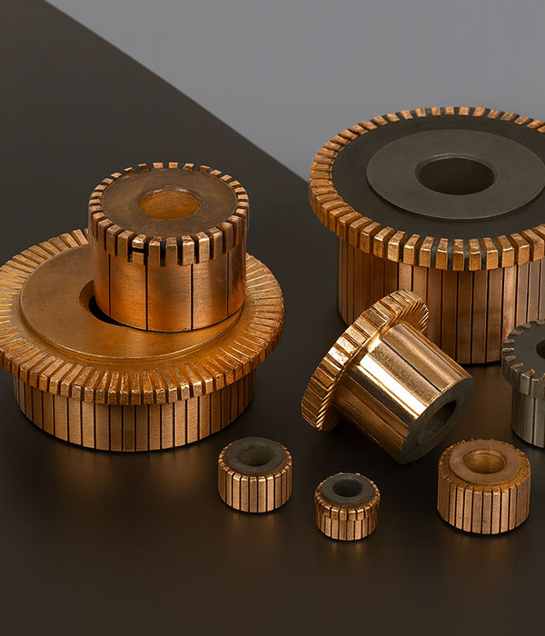
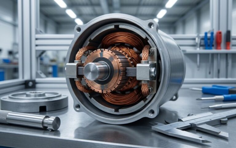
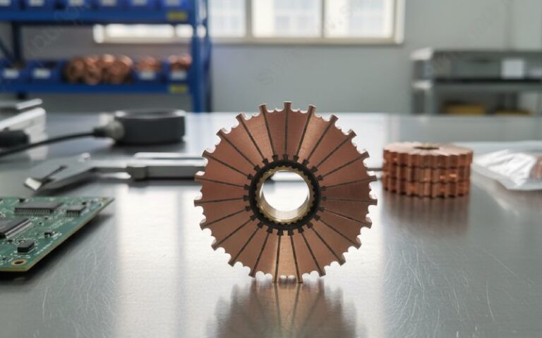
Built-to-Print: Core Elements in a Commutator Assembly
Bars / Segments
Copper segments carry current and switch coils. We review pitch, bar thickness, and cross-sections to ensure structural integrity and thermal margin.
Insulation System (Mica / Micanite)
We process insulation thicknesses typically 0.6–1.5 mm, and validate that the assembly withstands thermal cycling and centrifugal forces without delamination.
Hub and Risers
We manufacture riser configurations (hook, shell, planar) to maintain winding accessibility and mechanical balance at speed.
Surface & Film Formation
Copper surfaces are turned and undercut to support rapid formation of a stable commutator film—reducing noise, brush bounce, and abnormal wear.
Material Recommendations That Match Real Duty Cycles
Copper & Alloy Options
We use high-purity hard-drawn copper and can support silver-bearing copper (0.03%–0.08% Ag) when strength at operating temperature is critical.
Undercutting & Insulation Recession
Our automated undercutting ensures mica recedes below the copper surface after turning, so brushes ride primarily on copper/film rather than bare mica.
Environment Considerations
Stable commutator film formation is strongly tied to operating conditions. When reviewing your design, we flag risks related to:
Extreme humidity profiles (very dry air or highly humid duty)
Oils, vapors, or dust contamination
High altitude operation (cooling and arcing risks)
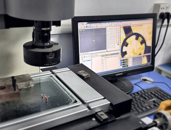
Quality Control That Protects Commutation Stability
Diameter, Runout & Concentricity
Runout shows up immediately as sparking and uneven wear. Every unit is checked before shipment to ensure it meets your drawing tolerances.
Pitch & Indexing Consistency
We monitor segment pitch uniformity and indexing accuracy so each bar is exactly where your drawing specifies—reducing local heating and unbalanced forces.
Surface Finish
We supply a finely turned surface finish (typical Ra 0.4–0.8 µm) followed by strict cleaning, so parts are ready for controlled run-in.
Dynamic Balancing
Every commutator undergoes dynamic balancing to protect brushgear and windings. We can follow balancing grades such as G2.5 / G1.0 as required.
Common Drawing Mistakes We Catch Early
Excessive segment voltage
Ignoring the ~20 V/segment guideline increases flashover risk. We may suggest more segments or geometry changes.Too-small segment pitch
Pushing pitch below manufacturable limits (often < 4 mm) can cause overheating and tooling instability.Brush current density mismatch
Designing standard carbon brush systems for metal-graphite levels (> 12 A/cm²) accelerates wear. Too low can also harm film formation.Runout/vibration underestimated
Loose concentricity control leads to brush chatter and abnormal sparking.Wrong copper grade for heat
Standard copper may soften in high-heat duty; silver-bearing options can be more appropriate.
How to Get an Accurate Quote Fast
What to send
Technical drawing (CAD/PDF) with dimensions + tolerances
Rated voltage / current / speed
Duty cycle and overload requirements
Environment: temperature, humidity, contaminants, altitude
Target quantity: prototype / pilot / mass production
If available: existing sample, photos, test issues, failure symptoms
What you’ll receive
Clarifying questions (if any)
DFM notes (manufacturability risks + recommended changes)
Quotation and lead-time proposal
Why Choose XDC for Custom Commutator Manufacturing?
We are not just a factory; we are your technical partner in commutator design realization. As a specialist manufacturer in China, XDC offers:
DFM Support
We review your electromagnetic and thermal requirements to ensure the design is manufacturable and cost-effective.
Material Alignment
We align copper, insulation, and molding compounds to your specific application and supply chain needs.
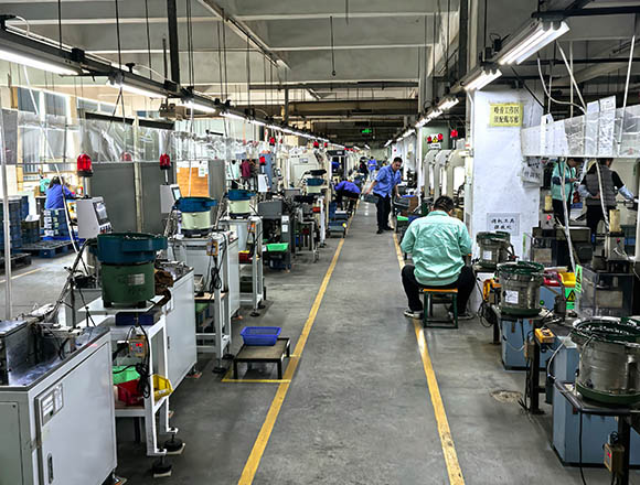
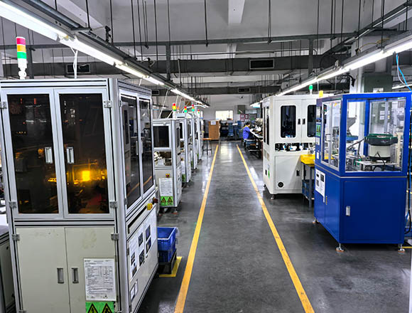
Controlled Manufacturing
Precision turning, mica undercutting, balancing, and inspection are all performed under one roof.
Application-Specific Tuning
Experience in industrial drives, traction, mining, and low-voltage high-current collectors.
Ready for a DFM Review and Factory Quote?
Upload your drawings/specs and we’ll respond with DFM notes and a quotation within 12 hours (business days). If you need an NDA first, request it and we’ll sign before file transfer.
* We understand your drawings and 3D files are sensitive. We can sign an NDA before file transfer. Files are used only for engineering review and quotation, and can be deleted upon request after the project is quoted or completed.
WhatApps
+86 17820674273
Address
Taixing Science and Technology Park, No. 3 Taixing Road, Dongguan City, Guangdong Province
Commutator DFM & Manufacturing FAQ
A: We are an OEM manufacturer. We don’t design motors from scratch, but we provide DFM support to help your commutator drawing move into stable production.
A: We follow your drawing and validate segment pitch and grouping against voltage/current requirements before tooling is frozen.
A: Typical references: 5.5–6.5 A/cm² for standard industrial carbon brushes; up to 8–12 A/cm² for electrographitic applications; and 12–30 A/cm² for special heavy-duty low-voltage systems with appropriate structures.
A: Yes. We review peripheral speed targets and mechanical stresses, then align balancing and runout controls to your RPM and duty.
A: A drawing (CAD/PDF) plus voltage/current/speed, duty cycle, environment, and target quantity is the fastest path to an accurate DFM review and quote.
Related Resource
At XDC, we share our deep insights into commutators, manufacturing processes, and industry experience on our blog. We invite you to explore these articles to learn more about our expertise.

Commutator Sparking and Wear: Why Brushes Must Align With the Motor Neutral Plane
The motor neutral plane is the running position where the coil under the brush can reverse current with the…
DC Motor Squealing Noise: Is It the Carbon Brush or the Commutator?
When a DC motor starts squealing, most people replace the brushes first. Sometimes that works. Sometimes the noise goes…
How to Check a Commutator for Roundness or Runout
Most bad readings start before the indicator touches copper. That is usually the whole job, really. Not the gauge.…


