What Is a Commutator? A Guide for DC Motor Buyers & Engineers
Table of Contents
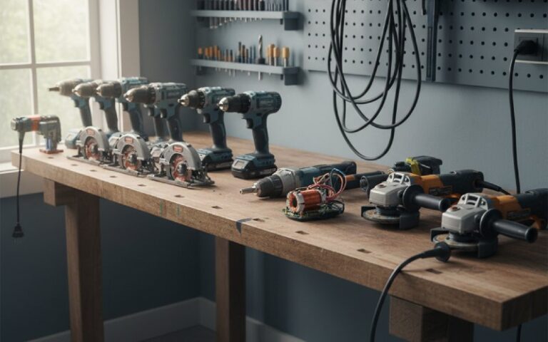
1. Quick Overview: Why Commutators Matter in Real Projects
If you buy or design DC motors or DC geared motors, the commutator is one of those parts you never see once the motor is assembled, but it quietly decides:
- How long the motor runs before brush change
- How much electrical noise you fight in your EMC tests
- How smooth the torque feels in your gearbox
- How often you get service calls from the field
So it’s worth understanding what this component actually does.
At its core, a commutator is a rotary electrical switch on the rotor of a DC motor or generator that periodically reverses the direction of current between the rotor windings and the external circuit.
That’s the short version. Now we unpack it and connect it to real-world decisions.
2. What Is a Commutator?
In a brushed DC motor (or DC gear motor), power comes in through two fixed carbon brushes and needs to reach coils that are spinning on the rotor. The commutator sits on the shaft and solves two problems at once:
- It brings current into the rotating windings through sliding contact.
- It reverses the current direction in each coil at the correct time, so the torque on the rotor keeps pushing in the same direction instead of alternating.
Without that timed reversal, the rotor would rock back and forth instead of spinning.
2.1 Commutator Definition
A concise engineering-style definition:
A commutator is a cylindrical assembly of insulated conductive segments mounted on the rotor of a DC motor or generator, used to periodically reverse current in the armature windings and provide a unidirectional output or torque.
You can think of it as a mechanical rectifier: it turns the AC-like current in the rotating coils into DC at the terminals, or vice versa, depending on whether the machine is acting as a motor or generator.
3. Commutator in DC Motors (and DC Geared Motors)
In a DC motor, the stator provides a magnetic field (permanent magnets or field windings). The rotor (armature) carries coils connected to the commutator. As the rotor turns:
- The commutator segments rotate under the brushes.
- Every half turn of the rotor, each coil’s connection swaps from one brush to the other.
- That swap flips the current in that coil, keeping the electromagnetic force on the rotor in a consistent direction.
In a DC gear motor, all of this is happening upstream of the gearbox. The commutator doesn’t “know” about the gears, but it strongly affects:
- Torque ripple at the gearbox input
- Brush dust and contamination inside compact gearmotor housings
- Life at low-speed, high-torque operation (the brushes sit longer on each segment)
So when you read “brushed DC gear motor, rated life 2000 hours” in a datasheet, the commutator/brush system is a big part of how that number was decided.
4. Commutation in DC Machines
“Commutation” is the process of reversing current in a coil as it passes under a brush.
Real-life commutation is not instantaneous:
- The brush usually spans 2–3 segments, so during the overlap, two adjacent segments are shorted together.
- The current in that shorted coil needs to change from +I to –I in a very short time.
- That rapid change induces a reactance voltage in the coil that opposes the change (Lenz’s law). If this voltage is not managed, you get sparking at the brush.
To keep commutation acceptable, DC machine designers use:
- Interpoles (commutating poles): small auxiliary poles between main poles that induce a voltage opposing the reactance voltage, improving commutation.
- Compensation windings in the pole faces on heavy-duty motors, to counter armature reaction and reduce brush arcing under varying loads.
- Correct brush grade, brush position, and segment geometry.
You won’t usually specify these directly as a buyer, but they explain why two motors with the same nominal ratings can behave very differently when run at high load or with frequent reversals.
5. Commutator vs Slip Rings
Both commutators and slip rings connect stationary circuits to rotating parts, but they behave very differently.
- Slip rings give you a continuous connection with no enforced reversal of current.
- Commutators are designed specifically to flip the current at defined rotor positions.
Here’s a buyer-focused comparison:
Table 1 – Commutator vs Slip Rings (Engineering & Purchasing View)
| Aspect | Commutator | Slip Ring | What it means for motor / gear motor selection |
|---|---|---|---|
| Basic purpose | Reverse current in rotor windings and provide DC at terminals | Transfer power or signals between stationary and rotating parts without altering waveform | For classical brushed DC motors and generators you want a commutator; for AC motors or signal transfer you want slip rings. |
| Typical machines | DC motors, DC generators, universal motors | AC generators, some synchronous motors, pitch control in wind turbines, rotating joints | If a “DC motor” spec sheet mentions slip rings, something is off. |
| Output / torque | Produces unidirectional torque or DC output | Does not shape the waveform; just passes it through | Commutator defines torque smoothness and speed range; slip rings mainly define continuity and noise level. |
| Wear parts | Brushes and commutator segments both wear | Brushes and rings wear, but usually with less arcing | Commutator systems tend to have higher maintenance needs, especially in dusty or high-duty applications. |
| Voltage / current limits | Practical limits on voltage, current density, and speed due to sparking and brush drop | Limits mainly set by ring diameter, insulation, and brush design | For high-power drives, slip rings with AC machines or brushless options are usually preferred. |
| Use in geared motors | Common in small and medium brushed DC gear motors | Rare (gearboxes usually pair with commutated DC or brushless motors) | If you need high-speed, low-maintenance gear motors, consider brushless options with electronic commutation instead. |
6. Working Principle of a Commutator (Simple Picture)
Let’s go with a basic two-pole DC motor example.
- Initial position
- One side of the armature coil is under a north pole, the other under a south pole.
- Current flows such that forces on the two sides create a torque in, say, the clockwise direction.
- Rotor rotates toward 90° (neutral plane)
- Torque on that particular coil reduces.
- Meanwhile, other coils (in a real motor) are producing torque, so total torque remains fairly steady.
- At around 90° mechanical
- The brushes line up at the geometric neutral.
- The brush is spanning two segments that belong to adjacent coils.
- The coil that just passed the neutral is shorted under the brush; its current is forced to change sign.
- After 180° of rotation
- That coil is now under opposite poles.
- But the current has been reversed by the commutator, so the electromagnetic torque direction is still clockwise.
Multiply this by many coils and segments and you get smoother torque and lower ripple. More segments → finer switching → better torque smoothness, but higher manufacturing effort and more things to control.
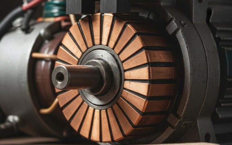
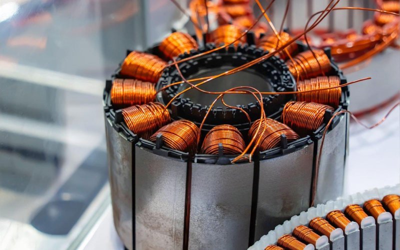
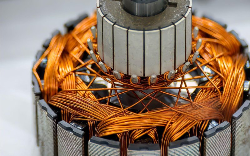
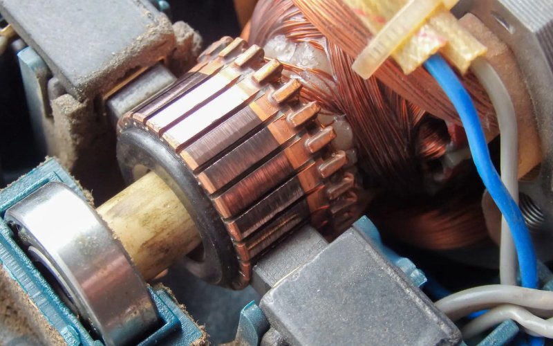
7. Construction of the Commutator
A practical commutator consists of:
- Copper segments (bars)
- High-conductivity copper or copper alloy.
- Each segment connects to one or more armature coils.
- Insulation between segments
- Traditionally mica, now also plastics and resins.
- Provides electrical isolation while handling temperature and mechanical stress.
- Support / clamping structure
- Segments may have a dovetail profile or be retained by glass-fiber bands or steel shrink rings.
- Industrial commutators can be refilled (individual segments replaced); small motors use molded, non-repairable units.
- Brush gear (not strictly part of the commutator, but always in the same conversation)
- Carbon or copper-graphite brushes in holders with springs.
- Brushes are sized so the contact area spans a controlled number of segments and keeps contact pressure stable.
On critical equipment like traction motors or high-speed drives, commutators may undergo spin testing or “spin seasoning” to ensure segment stability under centrifugal forces.
For a gear motor buyer, this is mostly invisible, but it does show up in lifetime and high-speed limits.
8. Operation of the Commutator in Motor and Generator Modes
The mechanical part of operation is always the same; what changes is what you care about at the terminals.
- Motor mode
- DC supply is applied across the brushes.
- The commutator routes this DC into the rotating coils, flipping current each half turn to keep torque in one direction.
- Generator mode (dynamo)
- Mechanical torque spins the rotor.
- Coils see a magnetic field and an AC-like induced voltage.
- The commutator acts as a mechanical rectifier, presenting a pulsating DC voltage at the brushes.
Some universal motors actually run from AC but still use a commutator, relying on the fact that both field and armature currents reverse together so torque stays in the same direction.
9. Types of Commutators
Engineers usually classify commutators in a few ways. Two that matter for motor buyers are geometry and construction method.
9.1 Split-Ring and Segmented Commutators
- Split-ring (2-segment) commutators
- Very simple, often in small educational motors or toys.
- Two half-cylindrical segments insulated from each other.
- Good for demonstration and low-power tasks.
- Segmented commutators
- Many narrow segments, each tied to a coil or coil group.
- Used in most practical DC motors and generators from a few watts up to large industrial machines.
More segments mean:
- Lower torque ripple
- Better commutation at higher speeds
- More complex manufacturing and balancing
9.2 Hook-Type Commutators
Hook-type commutators use hook-shaped ends on the segments so the coil ends are wound and hooked mechanically onto the commutator, often with arc-shaped grooves to protect the enamel wire.
They show up where you want:
- Reliable coil termination at high production rates
- Better tolerance to thermal expansion and vibration
- Compact geometries (common in small, high-speed motors used in tools, appliances, and some gearmotors)
9.3 Molded vs Built-Up (Refillable)
Another practical classification:
- Molded commutators
- Segments embedded in thermoset or thermoplastic.
- Not designed to be repaired; if it’s damaged, you replace the rotor.
- Very common in low- to medium-power DC gear motors.
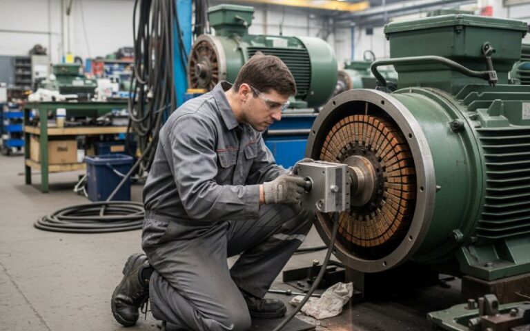
- Built-up, refillable commutators
- Segments individually clamped on a hub with mica insulation.
- Damaged segments or insulation can sometimes be replaced; surface can be machined.
- Used in larger industrial machines where the rotor is too costly to discard.
At XDC, we typically use Hook-Type commutators for our high-speed power tooI motors because they handle vibrationbetter, while our precision gear motors use molded segmented commutators for smoother torque.
10. Properties of a Good Commutator (Engineering View)
Key design parameters you may see indirectly in technical discussions:
- Segment material and hardness
- Copper alloys chosen for conductivity vs wear vs machinability.
- Segment count
- More segments → smoother torque and lower ripple, but also higher complexity and tighter tolerances.
- Diameter and surface speed
- There is a practical limit on peripheral speed to keep brush friction, heating, and arcing under control.
- Brush grade
- Pure graphite vs copper-graphite mixtures, tuned for current density, voltage, noise, and wear.
- Surface finish and runout
- Too rough → high wear and noise.
- Too much runout → brush bounce and sparking.
You probably won’t see these numbers in a basic datasheet, but they’re what the motor manufacturer is juggling in the background.
11. Functions of the Commutator (Summarized)
To tie the theory back to everyday work, here are the main functional roles:
- Reverse current direction in armature coils at the correct rotor angle.
- Produce unidirectional torque in motors and DC output in generators.
- Maintain moving electrical contact between stationary power leads and rotating coils via brushes.
- Segment the armature to prevent direct short circuits between coil ends.
- Shape the torque ripple characteristics, together with winding layout and number of poles.
12. Applications of Commutators
Commutators appear in:
- Brushed DC motors for conveyors, small pumps, medical devices, AGVs, door openers, etc.
- DC gear motors, where a brushed DC motor with a commutator is integrated with a gearbox for higher torque at low speed.
- DC generators / dynamos in legacy systems and some specialty power supplies.
- Universal motors in household appliances and power tools (AC supply but commutator-based construction).
At higher powers and in many new designs, commutator machines are being replaced by:
- AC induction or synchronous motors with inverters.
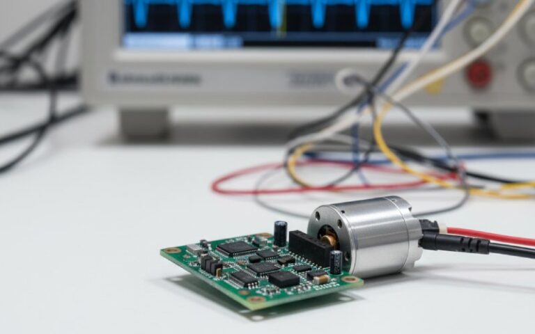
- Brushless DC motors (BLDC) that use electronic commutation instead of mechanical commutators.
13. Limitations of Commutators
There’s a reason so many new platforms move to brushless solutions. Commutators bring several constraints:
- Wear and maintenance
- Brushes and segments wear by friction.
- Brush dust can pollute compact housings or gearboxes.
- Voltage drop and losses
- The sliding contact has a brush drop (often a few volts), which is painful in low-voltage, high-current designs.
- Sparking and EMI
- Switching induces arcs and broadband electromagnetic noise.
- Problematic in explosive atmospheres and sensitive electronics.
- Speed, voltage, and current limits
- Above certain surface speeds, brushes start bouncing.
- There are hard practical limits on current density and voltage per segment.
- Environment sensitivity
- Humidity, dust, oil mist, and vibration all affect brush life and commutation quality.
None of this makes commutators “bad”; it just means you need to match the technology to the job.
14. Typical Commutator Problems in DC Geared Motors
Here’s a quick troubleshooting-style table. Handy for both engineers and purchasing teams trying to interpret field feedback.
Table 2 – Common Commutator Issues and What to Look At
| Symptom in the field | Likely technical cause | Impact on system | What engineer / buyer should check |
|---|---|---|---|
| Excessive sparking at brushes | Poor commutation (wrong brush grade, incorrect brush position, overload, missing/interpolated poles in larger machines) | Brush and commutator wear, possible EMC issues, heating | Verify operating point vs rating; ask supplier about brush grade and commutating pole design; check supply ripple. |
| Dark, uneven commutator surface with grooves | Contaminants, wrong brush material, insufficient surface finish, misalignment | Reduced life, noise, inconsistent torque | Review IP rating and environment; check if motor is being used beyond rated load or with frequent reversals. |
| Short brush life in gear motors running at low speed with high torque | High current density at low speed, poor cooling, brushes sitting too long on each segment | Frequent maintenance, downtime | Consider higher-rated motor, different gear ratio, or brushless alternative for that duty cycle. |
| Audible crackling and radio interference | Strong arcing during commutation | EMC test failures, interference with nearby electronics | Ask for versions with better commutation, filters, or move to electronically commutated BLDC where feasible. |
| Sudden failure after mechanical shock | Cracked or shifted commutator segments, damage to coil terminations (especially in hook-type designs if overloaded) | Motor stops or becomes noisy, possible internal short | Review shock and vibration conditions; confirm with supplier whether motor has been validated for that profile. |
15. Practical Notes for Buyers and Engineers
When you’re evaluating DC motors or DC gear motors that use commutators, a few practical questions help:
- Rated life and duty cycle
- Is the life rating based on continuous duty, intermittent duty, or a specific load profile?
- How does brush life change if you reverse frequently?
- Brush and commutator materials
- What brush grade is used?
- Are there optional brush grades for low-noise or high-current applications?
- Commutation quality
- Any data on brush sparking, EMI performance, or compliance with EMC standards?
- For higher power, ask if there are interpoles or compensation windings involved in the design.
- Environment and protection
- Is the gear motor sealed enough to keep brush dust away from your mechanism?
- What’s the recommended cleaning or maintenance interval?
- Alternatives
- For high duty, high speed, or hard-to-access locations, check whether a brushless DC gear motor with electronic commutation offers a better total cost, even if the piece price is higher.
This is where the commutator stops being an abstract classroom part and becomes a line item in your cost-of-ownership calculations.
16. Conclusion: Commutator
The commutator is the small copper cylinder on a DC motor shaft that quietly manages current reversal, torque direction, and a chunk of your maintenance budget. It:
- Reverses rotor current at the right angle
- Lets the motor deliver steady torque or DC output
- Introduces wear, losses, and some limits that you need to respect
For many compact DC gear motors, especially in cost-sensitive applications, a commutated brushed design is still a solid choice. For higher duty or highly regulated environments, brushless and AC alternatives are taking over.
Understanding what the commutator does – and what it needs to stay healthy – makes it much easier to have concrete, technical conversations with suppliers and to choose the right motor technology for your next project.
17. FAQ
Q: What is the main function of a commutator?
The main function of a commutator is to reverse the current in selected armature windings at the correct mechanical angle while maintaining electrical connection between the stationary supply and the rotating rotor. This controlled switching keeps the developed torque or DC output in one consistent direction.
Q: Why do DC motors need a commutator?
DC motors need a commutator because the rotor conductors move through alternating magnetic polarities. Without timed current reversal, the electromagnetic force on each conductor would change direction every half turn and the rotor would simply oscillate. The commutator turns the supply into properly phased currents that keep rotation going.
Q: Can a commutator be repaired?
Whether a commutator can be repaired depends on motor size and construction. Large industrial machines often use built-up commutators that can be skimmed, undercut, or even partially re-segmented. Small molded units in compact DC gear motors are usually considered non-repairable and are replaced as a complete rotor.
Q: Difference between commutator and brushes?
The commutator is a rotating copper segmented cylinder mechanically fixed to the rotor, while brushes are stationary conductive blocks that press on its surface. The commutator performs the actual current switching between segments; the brushes simply provide the sliding electrical interface between the external circuit and those segments.