Commutator Bars: Design Choices That Decide Whether Your DC Machine Behaves
If the commutator bars are wrong, everything downstream is just compensation. Brushes, interpoles, controls, maintenance tricks – they only hide the symptoms for a while. This piece focuses on the few bar-level decisions that actually shift reliability, commutation quality, and how often someone has to open the end-shield.
Table of Contents
1. What actually matters in a commutator bar
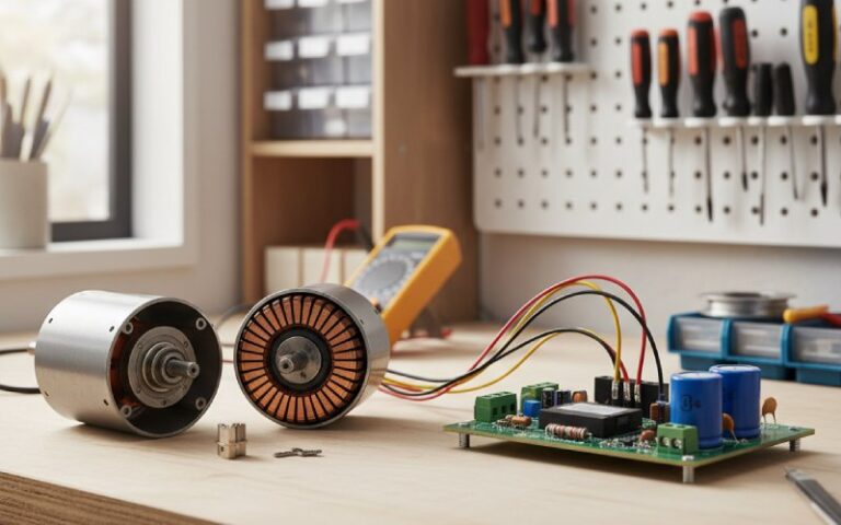
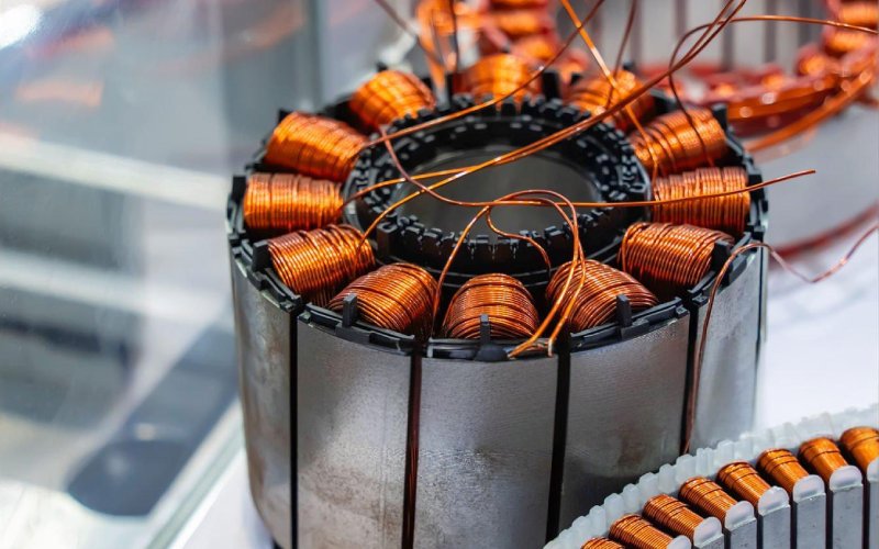
You already know the textbook story: wedge-shaped copper segments, mica between them, risers to the armature, brushes riding the surface. The real leverage sits in narrower places. Copper grade and hardness. Mica system and how it is treated in service. Bar geometry versus voltage per segment. Riser and solder integrity. Surface condition and the way the film stabilises with the chosen brush grade and duty cycle.
Most catalog copy lists these as separate items. In practice they interact. If the copper is too soft but the brush grade is also soft, the film may look acceptable while bars wear away faster than expected. A slightly high mica depth might be invisible at first, until carbon dust packs in the slots and suddenly flashover shows up in high-humidity days only. That kind of thing.
2. Bar material: copper that behaves under abuse
Most industrial DC machines still use hard drawn copper for commutator bars, with silver-bearing copper around 0.05% Ag on higher-stress designs for better strength at temperature. You can treat that as the baseline, but the way the bar material interacts with brush grade and peripheral speed is what counts.
Soft copper bars with high current density will smear, groove, and collect uneven film when paired with aggressive metal-graphite brushes. Harder bars run cleaner but push the brush toward vibration if the surface finish or concentricity is only mediocre. The spec sheet usually lists conductivity and hardness. The service technician cares about whether the bar edges chip during undercutting, whether ridges form at the trailing edge, and whether film colour spreads evenly across all bars instead of alternating bright and dull.
For retrofit projects, matching the existing brush grade is often safer than chasing the theoretically “better” copper alloy. If you change both at once, trends in wear rate and temperature become harder to interpret for the first maintenance cycle.
3. Mica and insulation: deciding whether the bars arc or stay quiet
Mica between bars is not there just to satisfy insulation tests. Its thickness, recess, and cleanliness decide how close you sit to flashover during overload and contamination. Classical design notes give around 0.8 mm mica thickness between hard drawn copper segments as typical. That value itself is rarely the issue; what you do in maintenance is.
Over time, the mica can become “high” when the commutator is turned on a lathe but the mica is not undercut again, leaving the insulation standing proud of the bars. High mica makes brushes ride on the insulation instead of copper, cuts the effective contact area, and pushes current density to the bar edges. Standard practice is to undercut the mica slightly deeper than its width so that the brush face never lands on it, and so that carbon dust does not easily bridge the recess.
If the recess fills with carbon and oil, it stops acting like insulation. You then get a new problem: debris bridging the slots, lowering surface insulation resistance and inviting flashover under transient conditions. Maintenance notes from commutator suppliers point out that flashover is much more likely when mica slots and risers accumulate conductive dirt. So the boring cleaning step is not cosmetic. It is part of the dielectric design.
Imperfect logic shows up here in practice: people sometimes push for deeper undercut “just to be safe,” but very deep slots can chip bar edges during brush bedding or under heavy vibration. That repair looks like an upgrade but may reduce mechanical robustness of the bar corners.
4. Geometry and bar count: voltage, speed, and how sharp the machine feels
For a given armature diameter, commutator diameter tends to fall in the broad range of 60–80% of the armature. That ratio is not aesthetic. It sets peripheral speed for a given rpm and constrains bar count for mechanical strength.
Too many bars give very narrow segments with limited root area, making them more sensitive to mechanical displacement and local heating at the riser. Too few bars mean higher voltage per segment, wider neutral zone, and a rougher commutation margin. Design guides often list “voltage between adjacent segments,” “number of coils,” and “number of brushes” together for a reason.
If you have ever seen a medium-speed machine upgraded for higher voltage without re-optimising commutator geometry, you already know the pattern. The machine passes no-load tests, looks fine at factory heat runs, then shows bar-edge burning and brush track instability at site during fast transients or field weakening. The math was correct. The practical commutation window shrank.
Peripheral speed also caps what spring pressures and brush grades can tolerate without lifting or chatter. Once your bar surface speed approaches the upper limit recommended by the manufacturer, everything becomes less forgiving: slot contamination, minor eccentricity, and small brush spacing errors show up as visible sparking instead of quiet operation.
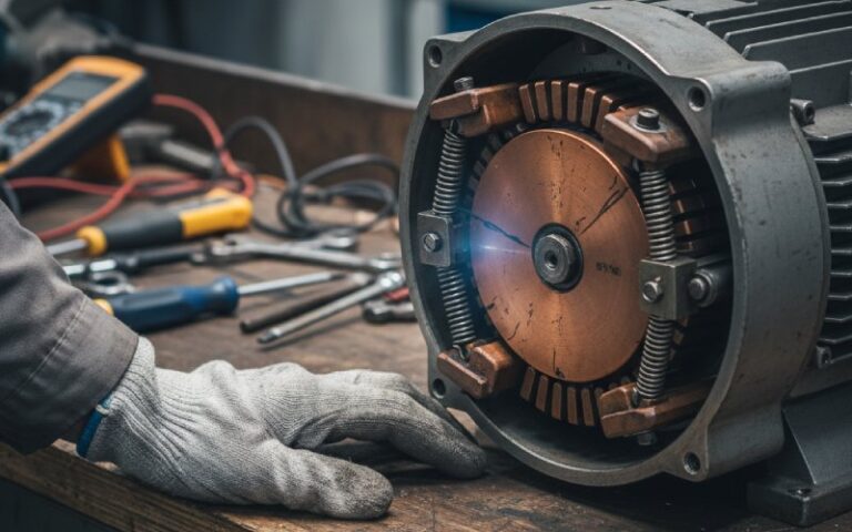
5. Riser connections and solder: where small resistance costs you a commutator
Each bar connects to the armature coil through a riser or lug, usually with a soldered joint. These joints sit at an awkward intersection: high current, cyclic heating, mechanical vibration, and sometimes careless rewinding. Design texts describe them in a sentence or two. Maintenance reports give them pages.
Loosened or high-resistance joints between the winding and the bar push local heating into the commutator. Burn marks often start at the affected bar and creep to neighbours as the problem progresses. The commutator surface then shows a repeatable pattern: one or a handful of bars discoloured and eroded, with brushes sparking heavily when those bars pass under, while the rest of the surface looks acceptable.
From a design and specification angle, you do not want this to be “someone else’s workmanship problem.” You can require controlled solder processes, specify maximum allowed temperature rise at the riser on test, and insist on bar-to-bar resistance checks with acceptable spread limits. In new builds or rewinds, make sure those numbers turn into recorded tests, not just a line in a procedure.
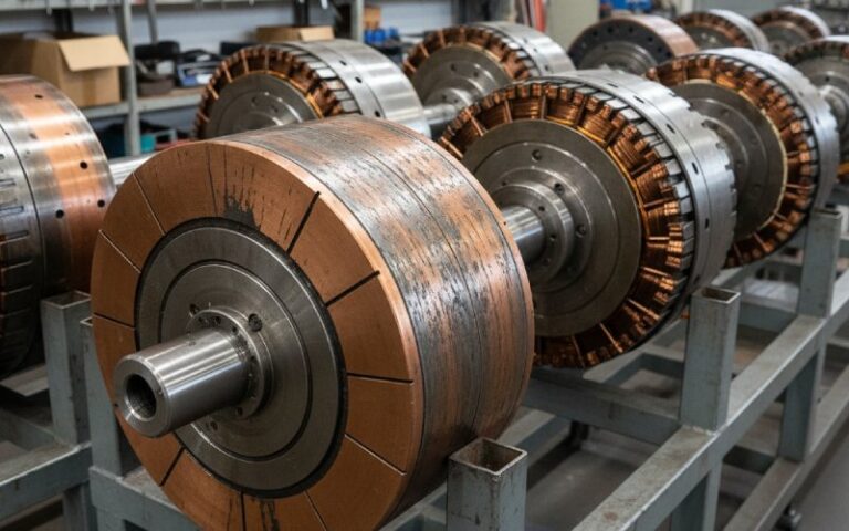
6. Surface condition and film: how the bars talk back to you
The copper itself is only half the interface. The graphite film formed by brush wear is the other half, and it tells you whether bars, brushes, and duty cycle agree with each other.
Carbon brush guides and supplier handbooks describe “normal” films as uniform light to dark brown, with smooth transitions and no streaks or patchy regions across the commutator. You can treat that as the reference picture. Deviations are diagnostics, not just cosmetic defects.
Flats on commutator bars – wide, flattened spots rather than continuous cylindrical surface – often trace back to faulty winding connections to the bar or mechanical issues that make some bars carry more current or load than others. Every time that flat passes under the brush set, contact conditions change abruptly, which reinforces the uneven wear. So the geometry and electrical connection feed back into the surface film, and the film feeds back into commutation quality.
A practical rule: when you see a striped or speckled film pattern, assume something upstream in design, installation, or operation is misaligned, rather than reaching first for a more exotic brush grade.
7. Design choices, what you get, and what to watch
The table below compresses the main bar-level decisions into something you can scan before signing a spec or a repair report. It is obviously simplified; that is intentional.
| Design element | Typical target or option | If you push it the wrong way | What to look for in service |
| Bar material and hardness | Hard drawn copper or low-silver copper alloy with adequate tensile strength and conductivity | Too soft: rapid wear, grooving, uneven film. Too hard relative to brush: vibration, streaky contact and noise at higher speeds | Ridges at trailing edges, rapid diameter reduction, alternating bright and dull tracks under the brushes |
| Bar width and bar count | Bar pitch chosen for acceptable voltage per segment and mechanical strength at rated speed | Too few bars: high segment voltage, wider sparking zone. Too many: narrow bars prone to distortion and poor heat dissipation | Localised burning at edges, especially near neutral, or bars that appear slightly “sprung” or misaligned in cross-section |
| Mica insulation and undercut | Mica thickness in the usual range with recess depth slightly greater than mica width after turning | Undercut too shallow: high mica, poor brush contact. Undercut too deep: chipping at corners, accumulation of debris in wide slots | Brush marks showing contact on mica, narrow bright copper lines along bar edges, or slots packed with carbon and oil |
| Riser and solder connection | Low-resistance, well-supported joints with controlled soldering and adequate mechanical support | Porous or cracked solder, loose risers, or strained leads cause local heating and fast bar deterioration | Single bars showing dark discoloration, pitting near one riser, or hot-spot readings that do not match current distribution |
| Surface finish and film | Smooth turned surface with correct roughness, then stabilized film using specified brush grade and run-in procedure | Rough turning, no proper run-in, or incompatible brush material lead to unstable film and intermittent sparking | Patchy film, concentric ridges, visible “steps” where different brush paths overlap |
| Peripheral speed | Within manufacturer’s recommended limit for brush grade and bar design at maximum operating speed | Excessive speed relative to design increases mechanical stress and makes brushes more sensitive to eccentricity and vibration | Evidence of bar movement, cracks in mica close to the bar corners, and recurring brush chatter marks at high load |
You can use this as a quick sanity check. If the visual symptom sits on the rightmost column, ask yourself whether the associated choice in the left columns was ever really controlled.
8. Specifying commutator bars in real projects
When you write or review a specification, try to convert vague phrases into testable points. Instead of “commutator suitable for heavy duty,” ask for copper grade and hardness range, maximum permissible peripheral speed, maximum voltage between adjacent bars, and the mica system details. It does not need to be poetic. Just specific.
For the insulation system, insist on explicit values for mica thickness, minimum undercut depth after final turning, and acceptable contamination level at factory release. For risers and joints, specify test methods for bar-to-bar resistance and the allowed spread across the circumference. Where possible, tie these to existing standards or manufacturer internal procedures, so you are not inventing a new rule set for every project.
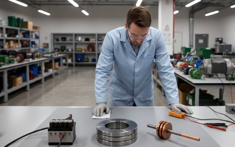
On acceptance testing, it pays to require at least three things: mechanical runout at the commutator surface, electrical tests that can catch open or shorted turns via bar-to-bar measurements or growler methods, and a visual inspection of surface finish and film formation after controlled run-in. The goal is not perfection; it is removing surprises at site.
9. When refurbishment makes more sense than replacement
A worn commutator with reasonable bar integrity can usually be turned, undercut, and edge-chamfered back into useful shape, provided you respect minimum diameter and bar height limits. Many maintenance documents from commutator and brush suppliers devote long sections to these routines because they extend machine life without needing a new armature.
Replacement starts to make sense when bars have shifted, risers are severely damaged, or the mica system shows widespread cracking and tracking that cleaning and machining cannot correct. At that point the bar stack has lost its mechanical unity or dielectric reliability. Repeated light repairs may actually increase risk because they consume copper and disturb stress distribution while the real defect remains.
During any refurbishment, keep an eye on cumulative dimensional loss. Each turning operation reduces bar height and diameter, which alters peripheral speed margin, brush contact area, and thermal capacity. It is easy to treat every repair as a small correction and forget that the stack has a finite life in millimetres.