Commutator Bar Failure Guide
How Alloy and Seasoning Reduce Slot Bar Marking, Copper Drag, and Burned Bars
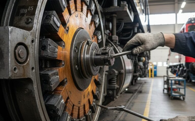
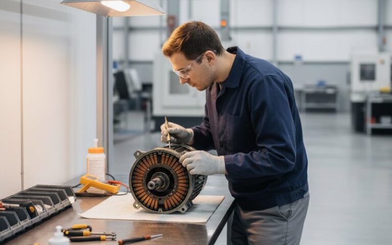
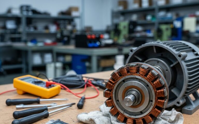
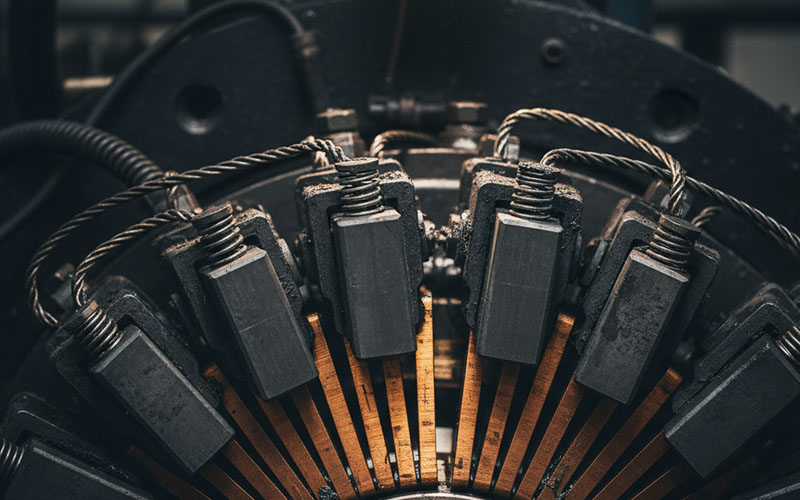
You already know what a commutator does.
You’ve seen dark bars, copper smeared across gaps, and brushes that quietly report every mistake.
So this is not an explainer.
This is about how commutator bar choices translate into failure patterns, and how to write a spec that keeps you out of the worst situations.
Table of Contents
1. When you buy commutator bars, what are you really specifying?
Most drawings just say “copper commutator bar” and move on.
In practice, you’re locking in much more than that.
Here are the levers that actually matter.
1.1 Copper system and silver content
Base material is high-conductivity copper, usually around 99.9% purity.
For hotter and heavier duty (traction, steel mills, big DC drives), we usually move to silver-bearing copper:
- small silver addition
- much better resistance to softening and creep at temperature
- conductivity still close to pure copper
Internal rule of thumb:
- Low-stress, low-temperature motors → plain high-conductivity copper is usually enough.
- High current density, frequent overload, hot enclosure → treat silver-bearing copper as the default, not a luxury.
1.2 Mechanical condition of the bar
It’s not just chemistry.
Bars are typically extruded and cold-drawn to final wedge profile. That cold work sets:
- hardness
- yield strength
- how the surface behaves once the brushes start cutting a film
We don’t leave this vague.
- For heavy-duty traction and mill-duty DC motors, we often target a Brinell hardness around 95–110 HB at the bar surface.
- For smaller industrial motors with moderate duty, a typical range might be 80–95 HB.
Too soft, and bars creep and smear under heat and load.
Too hard, and brushes pay the price.
If hardness isn’t on the drawing, expect batch-to-batch behaviour changes.
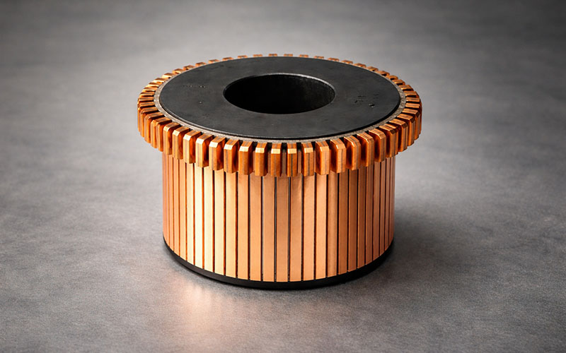
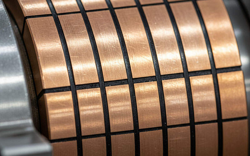
1.3 Geometry and insulation
Small geometry details show up later as very visible problems.
Things that matter:
- bar wedge angles and segment thickness
- hook / riser dimensions and position
- chamfer form at bar edges
- mica thickness between bars and at V-rings
For traction and heavy industrial DC motors, we usually define minimums for:
- segment thickness, to keep mechanical strength
- mica thickness, to keep insulation margin and mechanical stability
Leave this as “per supplier standard”, and you’ve already surrendered part of long-term behaviour.
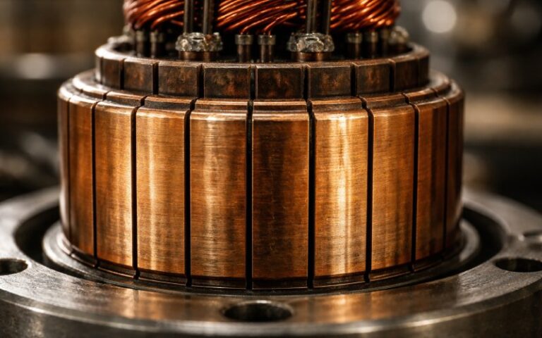
1.4 Core concept and pack construction
Key choices:
- steel-core vs shell-type
- mica type and grade
- resin system
- moulding or banding method
- how the copper–mica pack is compressed and baked
These drive how the pack moves during years of thermal cycles, overspeed events, and brush pressure.
1.5 Seasoning and spin testing
Two process blocks that decide whether the commutator settles in the factory or on your customer’s site:
- Static / compression seasoning
- multiple compressions and bakes on the bar–mica pack
- pressure, temperature, and time tuned to size and duty
- Spin seasoning / overspeed testing
- running at or above operating speed
- often at elevated temperature
- checking runout and bar movement before and after
If these steps are just “we do something in the oven” and “we give it a spin”, you will see movement in the field instead of in the test bay.
2. How commutator bar decisions show up as failures
Failures don’t walk in saying “silver content too low” or “seasoning incomplete”.
They show up as patterns on the surface.
Below are the patterns, what they usually mean, and where the bars get involved.
Add visuals here when you publish:
- real photos or clear sketches under each failure type
- engineers will match your images to the motor on their bench
Slot bar marking
- Visual: every other bar (or every few) darker and stained across the brush track.
- System causes usually include:
- uneven current distribution
- coil layout issues
- commutation zone too narrow for the duty
- Bar-side amplifiers:
- unstable bar pack that changes profile
- copper that scars quickly under local overload
- inconsistent undercut depth
Bar edge burning
- Visual: burned trailing edges of bars, often repeating at pole pitch.
- System causes:
- rocker not at electrical neutral
- incorrect interpole setting
- low spring pressure or mismatched brush grade
- Bar-side amplifiers:
- sharp or inconsistent chamfers
- softer copper deforming at edges
- poor roundness so a small group of bars carry most of the work
Copper drag
- Visual: copper smeared in the direction of rotation, sometimes bridging gaps.
- System causes:
- local overheating
- sparking and softening at the surface
- contamination that disturbs the film
- Bar-side amplifiers:
- copper with weak softening resistance
- shallow or contaminated undercut
- inadequate seasoning, so bars distort more under heat
Threading
- Visual: fine screw-like threads around the circumference in the brush path.
- System causes:
- metal transfer into the brush
- brush surface becomes a cutting tool and machines the commutator
- Bar-side amplifiers:
- very soft bar surface
- noisy machining marks left on the track
- unstable patina behaviour with the chosen brush grade
Burn marks from joints and leads
- Visual: hard burn near one or a small group of bars, growing with time.
- System causes:
- high resistance between armature leads and bars
- cracked brazes or welds
- Bar-side amplifiers:
- poor head / riser geometry
- inconsistent joint window or preparation
3. Failure pattern → action map (quick reference)
You already have your own troubleshooting slides.
This is a compact table focused only on what the bar and pack are telling you.
| Surface pattern on bars | What you see | Likely system issue (simplified) | Bar / spec action worth considering |
|---|---|---|---|
| Slot bar marking | Alternate bars darker or stained in the brush track | Uneven current distribution, coil layout, narrow commutation zone | Tighten bar-to-bar height and runout limits. Confirm bar material and seasoning can tolerate higher local reactance voltage without scarring. Improve undercut consistency. |
| Bar edge burning | Burned trailing edges, repeating at pole pitch | Off-neutral brushes, incorrect interpole strength, low spring pressure | Define chamfer geometry and surface finish. Set radial runout limits. Review bar hardness and silver content if edges deform early. |
| Copper drag | Copper smeared along rotation, bridging some gaps | Overheating, sparking, contamination | Switch to silver-bearing or higher-strength copper. Require deeper, cleaner undercut and a defined seasoning cycle. Put overload behaviour into the spec so the supplier knows what you expect. |
| Threading | Fine circumferential “threads” in brush zone | Metal pickup in brushes which then cut the bars | Tighten surface finish requirement. Avoid overly soft bar condition. Pair bar material with documented compatible brush grades. |
| Local flats / out-of-round | Flat zones or heavy burn in part of the track | Standstill overload, local hot spots, bar expansion that does not recover | Require spin seasoning at defined overspeed and temperature. Specify maximum permitted bar movement before and after spin. |
| Local burn at leads / risers | Hard burn near one or a few bars | High-resistance joints, cracked brazes or welds | Lock in head / riser geometry and a process spec for joints. Add routine joint resistance checks around the commutator. |
This is the piece that ends up on workshop walls: pattern, probable cause, and what to ask the commutator supplier for next time.
4. Tolerances that really move the needle
Tolerance culture comes in two flavours:
- “If the indicator doesn’t move much, we’re fine.”
- “We profile every commutator before and after seasoning and keep the plots.”
The second group has fewer surprises.
For industrial and traction-type DC motors, we usually care about:
- Radial runout (TIR) on the brush track
- Bar-to-bar height variation
- Gap depth and width after undercut
- Bar movement during seasoning and spin test
Example target ranges we often use (not one-size-fits-all):
- For mid-size industrial commutators, total indicated runout on the brush track held around 0.02–0.05 mm (0.0008–0.002 in).
- Bar-to-bar height variation kept down in the 0.005–0.01 mm range.
- Undercut depth in the 0.5–1.2 mm range depending on bar size and brush grade.
- Absolute bar movement after seasoning and spin typically limited to ≤0.01–0.02 mm.
The exact values depend on:
- diameter
- maximum speed
- mechanical duty
- brush block layout and brush grade
The point is simple: if runout, bar-to-bar height, gap depth, and bar movement aren’t on the drawing and aren’t in the test plan, they are at risk.
5. Turning this into a usable commutator bar spec
Here is how we usually structure bar and pack requirements for serious DC applications.
5.1 Copper alloy
Make a clear decision:
- high-conductivity ETP copper or
- silver-bearing copper with defined silver content
Lock in:
- silver content range
- max impurity levels relevant to your duty
Reference known standards where helpful, but keep the performance intent in plain language on the drawing.
5.2 Mechanical properties
Specify:
- hardness range at the bar surface (for example, 95–110 HB for heavy duty)
- supplied condition:
- cold-drawn to final profile
- any permitted stress-relief operations
5.3 Geometry and insulation
On the drawing, include:
- minimum segment thickness
- minimum mica thickness between bars and at V-rings
- wedge profile with prime dimensions
- hook and riser details
- chamfer form and size
- undercut depth and tolerance
This is where commutation behaviour, mechanical robustness, and insulation margin intersect.
5.4 Pack manufacturing process
Define at least:
- whether bars must be extruded and cold-drawn (instead of machined from plate for high-duty jobs)
- core type (steel / shell)
- mica type and resin system
- moulding and curing method
Scrap rate and copper consumption can be optimised later. Stability and repeatability come first.
5.5 Seasoning and spin testing
For traction and industrial motors, we typically require:
- a written seasoning cycle:
- number of compressions
- bake temperatures and dwell times
- a spin test:
- speed (as a percentage above rated)
- duration
- acceptance criteria for:
- runout increase
- bar movement
- any surface defects
These can live on the drawing or in a controlled spec referenced by the drawing.
5.6 Electrical tests
At minimum:
- inter-bar insulation test at defined voltage
- to-ground insulation test
- surge / impulse tests for harsh or switching-heavy systems where needed
6. Supplier checklist – with our own standards built in
Use this section directly in audits and vendor reviews.
Each point has two parts:
- What to ask a supplier
- Our standard (how we handle it in practice)
Q1. How do you control copper chemistry for commutator bars?
What to ask a supplier
- “Which copper grades do you use for commutator bars?”
- “How do you verify composition for each batch?”
- “What is your typical silver content range for high-duty commutators?”
Our standard
- We use defined high-conductivity or silver-bearing copper grades tied to international standards.
- Each batch has a mill certificate with copper purity, silver content, and key trace elements.
- Batch ID and chemistry are traceable to each commutator serial number.
Q2. What hardness range do you deliver at the bar surface?
What to ask a supplier
- “What is your typical hardness range at the brush track?”
- “Do you verify hardness on each batch or only at initial qualification?”
Our standard
- We define hardness windows matched to motor duty and brush system.
- Hardness checks are part of routine QC, not just type testing.
- Any out-of-range hardness triggers investigation and segregation.
Q3. What does your seasoning process look like, step by step?
What to ask a supplier
- “How many compression / bake cycles do you use?”
- “What temperatures and dwell times?”
- “How do you confirm the pack has stabilised?”
Our standard
- We run defined compression and thermal cycles based on size and application.
- Temperature, time, and pressure are logged per batch.
- Stabilisation is confirmed by runout and bar movement checks before and after seasoning.
Q4. Do you spin test each commutator of this size? At what speed and temperature?
What to ask a supplier
- “What percentage above rated speed do you use for overspeed tests?”
- “Do you perform hot spin tests or only at ambient?”
- “What is your scrap criterion after spin?”
Our standard
- Above a defined diameter, every commutator is spin-tested.
- Test speed is set above rated speed with a safety margin.
- For critical motors, we perform hot spin tests at elevated temperature.
- We set clear scrap limits for:
- runout increase
- bar movement
- visible damage
Q5. How do you measure runout and bar movement?
What to ask a supplier
- “Which instruments do you use to measure bar-to-bar height and runout?”
- “What sampling density around the circumference?”
- “Do you keep records over time?”
Our standard
- We use dial or electronic probes and, for larger units, non-contact sensors on the brush track.
- Measurements are taken at multiple axial locations.
- Data is stored with commutator serial numbers for traceability and trending.
Q6. How do you respond to field cases with copper drag, threading, or repeated bar edge burning?
What to ask a supplier
- “When a unit comes back with surface failures, what is your root-cause process?”
- “Do you adjust material or process based on these cases?”
Our standard
- We ask for photos and basic operating data and inspect returned units when possible.
- We analyse:
- bar material and hardness
- undercut condition
- runout and bar profile
- If the root cause tracks back to bar material or manufacturing, we adjust our process and update customer specs where needed.
Q7. Can you share performance history for motors similar to ours?
What to ask a supplier
- “Do you have long-term field data for this duty?”
- “Any documented reduction in particular failure modes after design changes?”
Our standard
- We maintain application notes and failure statistics by motor type and duty.
- Where NDA allows, we share anonymised case histories showing which spec decisions reduced failure rates.
7. FAQ: Commutator bars, materials, and specs
Q1. Do I always need silver-bearing copper for commutator bars?
No.
For low-stress, low-temperature motors, high-conductivity copper is usually sufficient and cost-effective.
We typically recommend silver-bearing copper when:
1. current density is high,
2. overloads are frequent, or
3. ambient and internal temperatures run close to limits.
In those conditions, silver-bearing copper holds hardness and shape better over time, which reduces softening-related failures such as copper drag and excessive bar movement.
Q2. How tight should commutator bar tolerances be?
There is no universal number, but for industrial and traction DC motors our common targets sit roughly in this region:
1. bar-to-bar runout on the brush track around 0.02–0.05 mm (0.0008–0.002 in),
2. bar-to-bar height variation down around 0.005–0.01 mm,
3. undercut depth typically 0.5–1.2 mm,
4. bar movement after seasoning and spin no more than 0.01–0.02 mm.
We tune these based on diameter, speed, duty, and brush arrangement.
Q3. Why does slot bar marking keep coming back even after a rewind?
If slot bar marking keeps reappearing, the root cause is rarely only in the copper.
Contributors usually include:
1. coil layout and current distribution
2. commutation zone too narrow for the loading
3. brush grade and spring pressure out of range for the duty
On the commutator side, unstable bar geometry, softening copper, and uneven undercut make the pattern appear sooner and more aggressively.
We treat persistent slot bar marking as a system problem and look at both the winding and the bar / brush combination.
Q4. Can better bar material solve all my commutation problems?
No.
Improved copper and well-controlled seasoning give more margin, but they do not replace:
1. correct brush setting,
2. proper interpole adjustment,
3. realistic loading,
4. suitable brush grade and pressure.
Material upgrades make sense when you are running near the limits of what standard copper can support. They are not a fix for basic setup errors.
Q5. What should I include on the drawing when moving to a new commutator supplier?
At minimum, we advise:
1. defined copper grade and silver content range where applicable
2. required hardness range at the bar surface
3. segment and mica thickness with minimums
4. wedge profile, hooks, risers, chamfers, and undercut details
5. radial runout and bar-to-bar tolerance limits with test method
6. seasoning and spin-test conditions with acceptance criteria
7. basic electrical tests and target values
8. traceability requirements and documentation to be supplied with each batch
With that in place, different suppliers are quoting against the same technical target instead of three different visions of “high-quality commutator”.
8. Ready to fix your commutator issues?
Don’t let bar specs stay as guesswork.
Here is how you can turn this into action:
- Download a Supplier Audit Checklist (PDF)
Use a ready-made list of questions from Section 6 plus example acceptance criteria. Take it into your next vendor meeting and see who can answer with data. - Request a Free Failure Screening
Prepare a clear photo of your commutator surface (slot bar marking, copper drag, threading, or bar edge burning), add basic motor and duty information, and send it through your preferred contact channel.
Your team (or ours) can then give a short written opinion on likely causes and whether a bar / spec change is worth considering.