Commutation in DC Machines: Designing for Quiet Brushes, Not Just Clean Waveforms
Commutation in a DC machine is nothing more than current reversal timed well enough that the brushes stay quiet, the copper stays flat, and torque stays predictable. When that timing is off, people say “the motor is bad” or “DC is obsolete”, but very often it is simply commutation that was never matched to the real duty of the machine.
Table of Contents
What Commutation Is Really Doing For You (Once You Already Know the Theory)
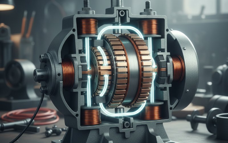
You know the definition: the commutator and brushes convert the alternating currents in the armature conductors into a unidirectional terminal current in a generator, and keep the armature current aligned with the field in a motor. In that sense the commutator is a mechanical rectifier in generators and a mechanical inverter in motors, but the underlying job is the same: reverse the current in a coil while it is shorted by the brush, without letting inductance fight back hard enough to cause sparking.
The documentation usually stops there. In real machines, commutation is also an air-gap management problem, a thermal problem at the sliding contact, and a compatibility problem between the drive waveform and the geometry of the commutator. That is where “works on paper” drifts away from “runs all year without brush dust everywhere.”
Ideal Versus Real Commutation
Ideal commutation is an almost boring situation. During the short interval when a coil is under a brush and its two segments are shorted, the current in that coil smoothly ramps from +Ia to −Ia. It passes through zero exactly at the mid-plane and finishes the reversal before the trailing edge of the brush leaves the outgoing segment. No sparking, no extra copper loss, no surprise heating.
Reality keeps adding small offsets. Armature reaction pushes the magnetic neutral axis away from the geometrical neutral. Saturation makes that shift load-dependent. The drive injects ripple into the armature current. Brush contact drops and commutator film are not identical from segment to segment. Each of these moves the induced reactance voltage slightly out of the “nice” direction, so the current in the shorted coil is slower or faster than you expected. That is over- and under-commutation, but in machines you see it as colors, sounds, and surface patterns, not as those neat straight lines on a chalkboard.
This is why design texts keep repeating that good commutation is helped when brushes are set along the true magnetic neutral axis for the intended operating point, not just along the mechanical neutral.
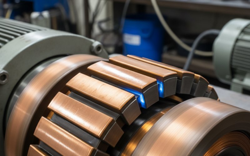
How Commutation Looks and Sounds at the Brushes
If you ignore waveforms and only stand in front of the machine, commutation shows itself first at the brush–commutator interface. Manufacturers and repair shops often classify sparking roughly in levels, from 0 (no visible spark) through small, intermittent yellow flashes, up to continuous ring fire around the commutator periphery.
A very faint, almost invisible blue glow at rated load is often acceptable. Distinct orange “tails” following the brushes mean current is refusing to leave a segment cleanly when the brush edge passes. A single zone of heavy sparking once per revolution points to a local geometric or contact problem, not a global design issue. These visual cues are crude, but they are faster than any oscilloscope if you are walking a plant floor.
Listening gives another angle. A healthy commutation zone tends to produce a steady, soft brush noise. When current reversal is fighting inductance, you get more irregular crackling and a harsher sound. It is not romantic; it is just energy being dumped into a tiny volume of graphite and copper in a very short time.
The Commutation Interval As a Design Space
If you strip away all the drawing detail, the commutation interval is just this: a coil with inductance L, carrying current that must reverse in time tc, while its terminals are clamped together through a brush resistance that is partly under your control. You also have a small “helper” voltage from interpoles or from shifted brushes, and a disturbing voltage from the armature reaction field.
The textbooks call the induced opposing voltage the reactance voltage. You rarely calculate it explicitly in day-to-day work, but you feel it when a machine that looked fine on no-load suddenly becomes noisy at full current. Raising brush resistance (carbon instead of copper, specific grades, contact pressure) stretches the current waveform and damps the worst of that induced voltage.
Interpoles and compensating windings work from the other side: they inject a small voltage across the shorted coil that helps the current go where you want it to during tc. Together, those measures are the standard “knobs” used to make commutation acceptable in production machines, and they show up in every serious source on improving commutation.
A Practical Table: What You See Versus What Is Probably Going On
Here is a compact way to connect what you inspect at the commutator with likely causes and quick checks. It is intentionally approximate; the point is to force you to think in commutation terms, not only in “this motor is bad” terms.
| Symptom at commutator and brushes | Likely electrical cause related to commutation | Likely mechanical or environmental contributor | Quick checks that actually help |
|---|---|---|---|
| Very faint blue glow at rated load, no visible tails, commutator evenly colored | Current reversal nearly complete within commutation period, reactance voltage modest, interpoles and brush resistance sized sensibly | Commutator round, good mica undercut, correct brush grade, holders aligned | Measure armature current ripple, verify brush temperature and wear rate over a full shift rather than just a short test |
| Short orange sparks at trailing edge of brushes, worse at high load | Late commutation: current still high in the outgoing coil when the segment leaves the brush, armature reaction shifting neutral | Brushes slightly off true magnetic neutral at that load, light commutator roughness, marginal spring pressure | Move brush rigging a few electrical degrees in both directions and observe change, check interpole polarity and air gap using standard tests |
| Heavy sparking around almost entire circumference, quickly darkening copper | Serious over- or under-commutation, often driven by excessive armature ripple or mis-sized interpoles, sometimes incorrect field connection | Worn or uneven brushes, contaminated commutator film, segment high spots, poor cooling raising contact resistance | Verify supply or drive waveform, check field connections against nameplate, measure commutator run-out, check brush grade against design documents |
| Sparking localized to one small angular region, repeating once per revolution | Local difference in commutation voltage on a few coils, often due to an open or high-resistance coil or segment | High or low commutator segment, local contamination (oil, dust), single damaged brush | Strobe the commutator to identify the segment, perform bar-to-bar test, inspect for mechanical damage or contamination at that location |
| Little visible sparking, but high brush wear and dark, streaked film | Commutation mostly acceptable electrically but with poor film chemistry; current density or humidity pushing brushes out of their comfort zone | Incorrect brush grade for duty, roughness at micro level, vibration, unsuitable ambient conditions | Review brush grade recommendations, adjust spring pressure, check vibration and bearing condition, consider slight change in brush current density |
None of this replaces measurements, but it keeps the discussion specific. You stop saying “it sparks” and start saying “it sparks late at high load with neutral not quite right.”
The Classic Levers: Resistance, Voltage, and Compensation
Most references group the improvement methods under three headings: resistance commutation, voltage or EMF commutation, and compensating windings.
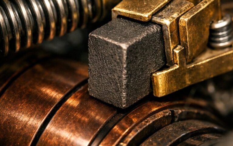
Resistance commutation is mostly about brush material and contact conditions. Carbon and graphite brushes add resistance in the short-circuited path, which helps to reduce the current more linearly during the commutation interval. You pay for that with additional copper loss and brush heating, so there is a trade: “sparkless at any cost” is not a real objective. Brush pressure, surface finish, and film all nudge that effective resistance in both directions during operation.
Voltage or EMF commutation uses an assisting voltage to push the current reversal. You can get that by physically shifting the brushes slightly forward or backward in the direction of rotation, or by using interpoles wound in series with the armature. Brush shift is simple and adjustable but tends to be correct only at one load point. Interpoles cost more to build but keep commutation under control over a wider current range, especially in larger machines.
Compensating windings are embedded in the pole faces and carry armature current, cancelling much of the armature reaction in the pole region. The idea is not beauty; it is to keep the flux in the commutation zone closer to what you assumed when you picked brush position and interpole strength. This becomes more relevant in heavily loaded machines with strong armature fields and where the user expects constant behavior from light to overload.
Neutral Plane, Armature Reaction, and Why “Set It Once” Is Not Enough
On no-load, the magnetic neutral axis sits roughly in line with the geometrical neutral. As armature current grows, the armature field distorts the main field and shifts the neutral. If you bolt the brush holders in place based on a no-load test and then never touch them again, you are designing for the wrong condition.
Good practice in many plants is to set brushes near the neutral that corresponds to a realistic operating point, usually at or near rated current, not at zero torque. Interpoles then help flatten the behavior so that light-load operation remains acceptable. If there are no interpoles, you are forced into compromise, and the machine may be slightly biased toward either better low-load or better high-load commutation, but not both.
Saturation adds another twist: the field shift with current is not linear, so neutral position may not move in a simple way with load. This is one reason two machines with nominally identical nameplates can behave differently when someone quietly rewinds the field or changes pole construction without re-tuning the commutation scheme.
Modern Drives, Old Machines
Most classic commutation discussions quietly assume a stiff DC supply. Many machines today are fed by rectifiers or chopper drives with significant ripple and high di/dt. The armature current is now a staircase or a ripple-rich waveform instead of a nearly constant value. That badly agitates commutation, because the reactance voltage in the shorted coil is proportional to di/dt.
Thyristor DC drives, for example, are well known for worsening commutator sparking if the machine was designed for smoother supply. Engineers then try to fix the symptom with brush changes or minor mechanical work, when the core of the problem is supply quality. Smoothing inductors, careful firing angle control, or a different drive topology sometimes help more than another round of commutator turning.
When you see a machine that behaved well on a test bench but misbehaves on the installed drive, this mismatch between assumed and actual armature waveform is usually high on the list of suspects.
Thinking About Commutation Failures Like a Designer, Not Just a Troubleshooter
A lot of field reports and even some papers treat commutator damage as a random outcome. In reality, it is linked to quite ordinary design choices: current density at the brush, segment width versus brush width, materials, cooling, drive type, and how aggressively armature reaction is neutralized.
If you think like a designer while troubleshooting, the questions shift a bit. Instead of asking only “what is broken,” you ask “what assumption about commutation was baked into this machine, and is the user honoring that assumption?” Maybe it was intended for near-constant current but is being cycled hard. Maybe interpoles were sized for one direction of rotation but the application reverses constantly. Maybe the air-gap has changed after a mechanical repair, moving the neutral enough to spoil your careful timing.
This also explains why a machine can run for years, then start to show sparking with no obvious electrical change. Mechanical wear and small alignment shifts gradually erode the conditions that once gave acceptable commutation. When someone then turns the commutator without re-checking brush geometry or neutral position, they remove the “memory” of the old, stable running condition.
A Short, Honest Summary
If you strip away the jargon, commutation in a DC machine comes down to this sequence: you ask a small, inductive coil to reverse its current in a very short time while it is shorted through a brush, and you try to stop that process from eroding copper and carbon faster than the business can tolerate. The official documentation describes the waveforms and phasor diagrams. The real work is choosing brush material, position, interpoles, compensating windings, and supply quality so that those waveforms actually appear in metal, not just in a notebook.
Once you look at commutation that way, brush trails and commutator color stop being mysterious symptoms. They become a rough but surprisingly reliable measurement of how well your design assumptions are surviving contact with real duty cycles, ambient conditions, and drives that rarely behave as ideal voltage sources.