Can 3D Printing Technology Improve Commutator Manufacturing?
3D printing can improve commutator manufacturing. But the gain is not where many people first look.
It does not really solve the finished brush-contact surface in one step. Not yet, at least not in a way most production teams would trust for broad use. What it does improve is the chain around that surface: tooling, fixtures, prototype bodies, low-volume variants, near-net copper preforms, and some repair or legacy-part scenarios where waiting for hard tooling makes less and less sense.
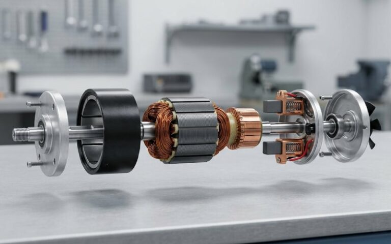
That distinction matters. A commutator is not just a copper shape. It is a sliding electrical contact system. So the manufacturing question is never only “can this be printed.” The real question is harsher: can it be printed, finished, assembled, and then survive contact pressure, current load, heat, vibration, and brush wear without creating a new problem upstream.
Table of Contents
Why Commutator Manufacturing Is Harder Than It Looks
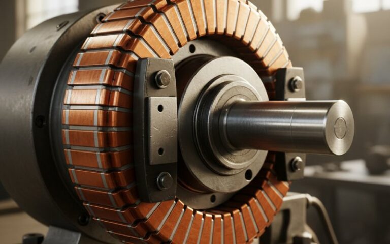
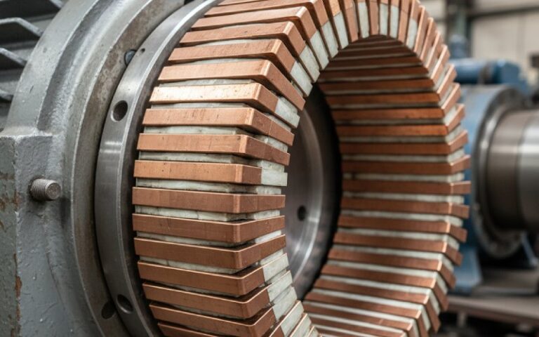
A commutator has a simple outline. The process behind it is not simple.
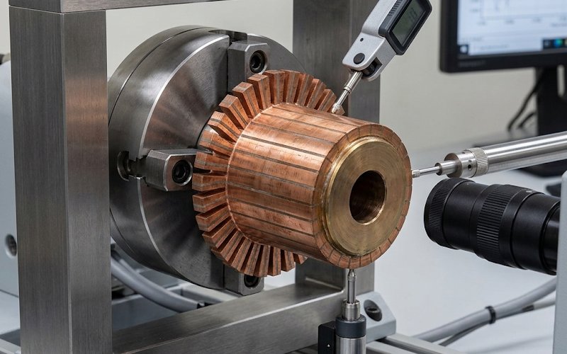
Each copper segment has to be electrically isolated. The geometry has to stay stable under rotation. The contact track has to run true. The insulation cannot sit proud of the copper surface. Burrs matter. Edge condition matters. Slot cleanliness matters. A small error on the bench can become heavy brush wear, unstable current transfer, noise, or visible sparking when the part is under load.
This is why conventional commutator manufacturing has stayed stubborn. It is not only a shaping process. It is a shaping-plus-contact-control process.
That is also why many “3D printing will replace machining” claims fall apart here. They focus on geometry and ignore the contact interface.
The Short Answer: Yes, but Mostly Through Hybrid Manufacturing
For most real applications, the best answer is hybrid manufacturing.
That means 3D printing handles the parts of the process where flexibility is valuable and surface contact is less critical. Conventional machining, grinding, slot finishing, and inspection then take over where precision electrical contact becomes non-negotiable.
In plain terms:
- Print the support work
- Print the prototype geometry
- Print some near-net copper where waste or complexity hurts
- Do not assume the printed contact track is ready for brushes
- Finish and validate the final surface like a real commutator, because it is one
This is the useful frame. Once that frame is clear, the technology becomes easier to judge.
Where 3D Printing Actually Helps in Commutator Production
1. Tooling, jigs, and fixtures
This is the lowest-risk entry point and, in many shops, the fastest return.
Commutator assembly and finishing often depend on custom holding, alignment, trimming, positioning, and inspection aids. These parts are usually low-volume, geometry-specific, and annoying to outsource in a hurry. That is exactly where 3D printing fits well. A printed fixture can cut setup friction, shorten trial cycles, and let the team revise a support tool without reopening a full tooling project.
For standard production this may sound small. It is not small when the line is waiting.
2. Prototype insulator bodies and design-validation parts
During development, the expensive mistake is often not in copper. It is in committing too early.
A printed body or non-contact structural component can help verify clearances, coil lead routing, assembly sequence, mechanical fit, balance envelope, and service access before the final production route is locked. That makes 3D printing useful even when the printed part never becomes the production part.
This is one of the more practical uses in commutator work. It saves the wrong tooling decision.
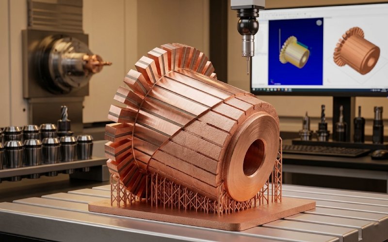
3. Near-net copper preforms for custom or low-volume parts
This is where the discussion gets more technical.
Modern copper additive manufacturing, especially powder-bed metal processes, has moved far enough that dense, highly conductive copper parts are no longer theoretical. In optimized conditions, printed pure copper has been reported at about 98.9% relative density and up to 100% IACS conductivity. Earlier work also showed printed pure copper around 94 ± 1% IACS. Those numbers are serious enough to matter. They move the debate away from “is printed copper conductive at all” and toward the harder question, which is surface behavior and process stability.
For commutators, that means a printed copper preform can be useful in low-volume or geometry-sensitive cases. Not because it leaves the machine ready to run, but because it gets the conductive mass close to final shape with less waste and more design freedom than some subtractive routes.
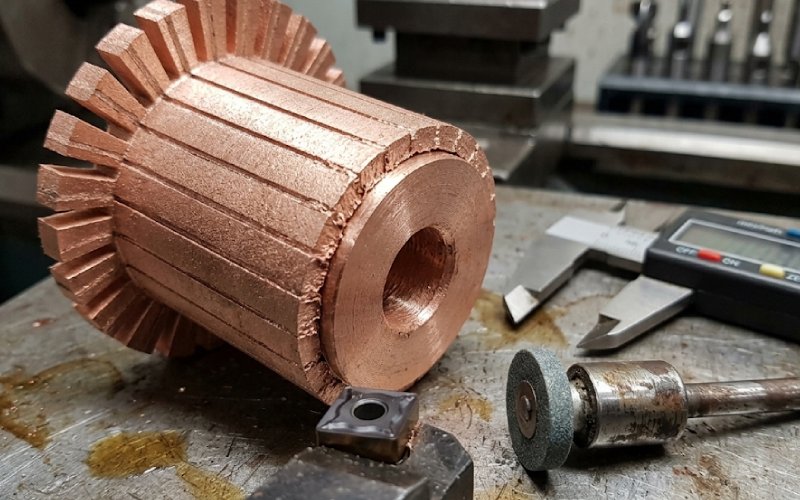
Then the real work starts. Turning. Grinding. Slot cleanup. Concentricity control. Surface conditioning. Inspection.
4. Legacy replacements and slow-moving spare parts
There is a narrow but important category where 3D printing makes more sense than it first appears: old parts, special variants, service replacements, and demand that shows up in bursts rather than clean forecasts.
In those cases, the argument is less about unit cost and more about avoiding hard tooling, reducing inventory exposure, and keeping lead time under control. Hybrid production models are often studied for exactly this reason: additive steps can make low-volume spare parts and custom parts more viable, while conventional finishing still protects final function.
That is not a universal win. It is a situational win. Still a real one.
Where 3D Printing Still Runs Into Trouble
Final brush-track quality
This is the wall.
The brush-contact surface has to meet a narrow operating window. Too rough and wear climbs. Too smooth and film behavior can turn unstable. High insulation between segments creates trouble. Surface geometry has to stay controlled across the full track, not only in one measured spot. Technical guidance for commutator and slip-ring service has long treated roughness, mica condition, seating, and surface checks as core reliability variables, not cleanup details.
Now put that beside additive copper. Even when conductivity is excellent, as-built surface finish is often not ready for sliding contact duty. One recent copper powder-bed study reported Ra around 8.27 µm in the as-built state before polishing. Other work shows that surface condition can vary strongly by orientation and process setup. In other words, the printed copper may be electrically promising while still being tribologically wrong for brush contact.
That gap is the central manufacturing issue.
Printed conductive polymers are still not a direct substitute
This point should be stated plainly.
If the plan is to use low-cost filament printing to make a production commutator, the conductivity gap is still too large. Published work has noted that highly conductive thermoplastic-based 3D printing filaments can be 3,750 times less conductive than copper before metallization. That makes them useful for mockups, some experimental fixtures, and selected plated concepts. It does not make them a drop-in material for the final current-carrying contact path of a production commutator.
So yes, there are things to print. The final brush track is usually not one of them, at least not without substantial downstream work.
Process Comparison: What Should Be Printed, and What Should Not
| Manufacturing task | 3D printing fit | Best use case | Main benefit | Main limitation |
|---|---|---|---|---|
| Assembly fixtures and gauges | Very high | Frequent changeovers, prototype assembly, inspection support | Fast revision, lower tooling delay | Wear life of the fixture must still be checked |
| Prototype insulator bodies or support forms | High | Fit checks, routing validation, design iteration | Faster development loop | Material may not match final thermal or dielectric behavior |
| Near-net copper preforms | Medium | Low-volume custom parts, obsolete replacements, unusual geometry | Less waste, more shape freedom, lower dependence on dedicated tooling | Final machining and surface finishing are still required |
| Full final brush track straight from the printer | Low | Experimental work only | Geometry can be formed | Surface, runout, burrs, insulation condition, and wear behavior remain limiting |
| Conductive-polymer printed commutator for production use | Very low | Concept models or plated trials | Speed and low setup cost | Conductivity and durability are far below copper-based production needs |
Cost, Lead Time, and Volume: The Decision Table Most Articles Skip
A technical yes does not always mean a manufacturing yes.
For commutator work, 3D printing becomes more attractive when part volume is low, geometry changes are frequent, tooling cost is hard to recover, or spare-part demand is uncertain. It becomes less attractive as volume rises and the design stabilizes. In high-volume standard parts, conventional routes still tend to win on throughput, repeatability, and per-part economics. In low-volume or slow-moving parts, additive steps can reduce tooling burden and shorten supply response even when the printed part still needs machining later.
| Scenario | Economic fit of 3D printing | Why it works or fails |
|---|---|---|
| Early-stage R&D and design validation | Strong | Design changes are frequent, and avoiding hard tooling matters more than piece price |
| Low-volume custom commutators | Good | Dedicated tooling is hard to amortize; near-net geometry and printed fixtures reduce delay |
| Legacy replacement parts | Good to very good | Demand is sporadic, inventory is expensive, and lead time often matters more than ideal cycle cost |
| Medium-volume stable products | Conditional | Hybrid use may still help in tooling and fixtures, but not always in the finished conductive part |
| High-volume standard commutators | Weak | Conventional production usually wins on throughput, consistency, and cost spread |
A simpler way to say it:
3D printing is strongest when uncertainty is expensive.
That could be uncertain demand. Uncertain geometry. Uncertain service life. Or just uncertain timing.
The Best Practical Route Today: A Hybrid Commutator Workflow
If the goal is a usable process rather than a lab demo, the route usually looks like this:
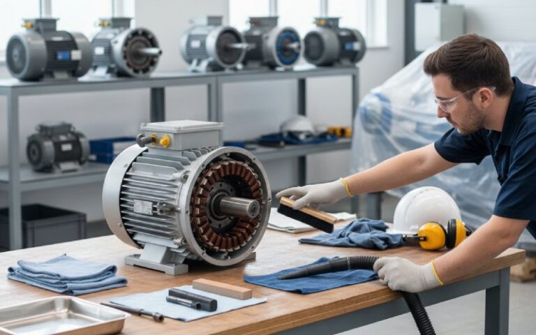
Step 1: Print the low-risk parts first
Start with fixtures, nests, inspection aids, routing guides, and prototype bodies. These give process value quickly and do not ask the printer to solve the hardest electrical-contact problem on day one.
Step 2: Use metal printing only where geometry or supply constraints justify it
If a copper preform is printed, leave material and tolerance strategy for downstream finishing. Assume the contact zone will need controlled machining. Assume slots will need cleanup. Assume the final track will need inspection beyond simple dimensional checks.
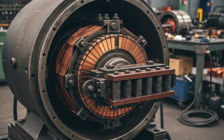
Step 3: Machine the contact interface as if it were the product, because it is
The commutator may contain many features, but the brush sees one thing first: the running surface.
So the finishing process has to control:
- surface roughness
- runout and concentricity
- segment edge condition
- burr removal
- insulation recession or undercut condition where required
- cleanliness before seating and test
This is the point where a printed part either becomes a real component or stays a prototype.
Step 4: Validate under operating conditions, not only with static measurements
Commutators fail in motion. Under current. Under heat. Sometimes only after enough brush travel has exposed the weak area.
So validation should include more than conductivity and dimensions. It should look at wear pattern, contact stability, temperature rise, visible sparking tendency, and surface change after run-in. Sliding electrical contact systems are sensitive to tribology and current at the same time; a good-looking surface before testing is not the same as a stable surface after testing.
When 3D Printing Is the Wrong Choice for Commutator Manufacturing
It is worth saying this clearly, because many articles avoid it.
3D printing is the wrong choice when:
- the part is already standardized and high-volume
- the geometry is simple
- the brush track quality requirement is tight and the printing step adds no real savings
- the process would still require almost the same amount of machining afterward
- the buyer is hoping printing will remove finishing, inspection, and tribology validation
If that is the situation, the printer may still help with tooling. It may not help with the commutator itself.
That is still useful. Just smaller in scope.
A Better Way to Ask the Original Question
Instead of asking:
Can 3D printing manufacture a commutator?
A more useful question is:
Which parts of commutator manufacturing benefit from additive methods, and where does conventional finishing still dominate?
Once the question is framed that way, most of the confusion goes away.
The answer becomes straightforward:
- Additive methods are good at flexibility, low-volume adaptation, complex support geometry, and near-net preforms.
- Conventional finishing still dominates the final sliding contact interface.
- The winning strategy, for now, is hybrid.
FAQ
Is 3D printing suitable for production-grade commutator segments?
Sometimes for the preform, rarely for the final brush-ready surface in one step. Production-grade use usually means printing the conductive mass close to shape and then finishing the running surface with conventional precision processes.
Which 3D printing process is most relevant for commutator development?
For non-conductive support parts, polymer-based printing is often enough. For conductive copper development, powder-bed metal processes are the more relevant route because they can produce dense copper with much higher electrical performance than conductive polymer printing.
Can a printed copper commutator reach acceptable conductivity?
Yes, the material side has improved a lot. Dense printed pure copper can reach conductivity close to, and in some optimized cases matching, annealed copper standards. But conductivity alone is not enough. Surface finish, porosity control, and brush-track stability still decide whether the part is usable.
Does 3D printing reduce commutator manufacturing cost?
In some cases, yes. Mostly when volumes are low, geometry changes are frequent, or tooling cost would otherwise dominate. In stable high-volume production, the economics often move back toward conventional methods.
Can 3D printing shorten lead time for custom commutators?
Usually yes, especially in development parts, fixtures, prototype bodies, and selected low-volume replacements. The lead-time gain often comes from avoiding dedicated tooling and from printing on demand, not from eliminating finishing.
What is the biggest technical barrier today?
The final sliding contact surface. A commutator can tolerate less uncertainty there than many other copper parts. That one surface carries a lot of the manufacturing risk.
Final Answer
3D printing can improve commutator manufacturing. It already does, in the right places.
Its strongest value today is not in printing a finished commutator and sending it straight to assembly. The real value is more grounded than that: faster tooling, faster iteration, low-volume flexibility, near-net copper geometry, and better support for spare-part or custom manufacturing.
For the final brush-contact track, though, the old rules still apply. Surface quality. Runout. Segment condition. Insulation control. Testing under load.
So the best answer is not “print everything.”
It is simpler.
Print what benefits from flexibility.
Machine what demands certainty.
Treat the contact surface as the product.