Technical Guide: Building Reliable Brushed DC Motors with Commutators
With a few practical hooks for real projects
This guide assumes you already know DC machine theory and you have a basic electromagnetic design on your side.
The goal is narrower and more practical:
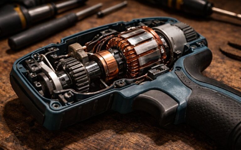
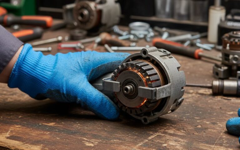
Build and assemble a brushed DC motor so the commutator, brushes, shaft, and winding behave like a stable system, not a pile of parts that fight each other.
Use it as a checklist when you:
- Develop a new platform
- Review or switch suppliers
- Debug a motor that “should be fine on paper” but keeps failing in the field
Table of Contents
1. Scope: what this guide actually covers
We do not redo magnetic design.
We do focus on the mechanical and assembly details that usually kill commutators and brushes early:
- Commutator specification
- Shaft fit and press-fit risks
- Armature build and joints
- Mica undercutting and cleaning
- Brush gear and neutral setting
- Typical failure patterns and how to avoid them
Even if you already have a commutator supplier, you can treat this as a structured list of questions to use with them.
2. Quick design snapshot (context only)
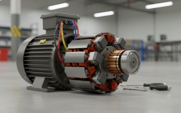
Take a compact industrial brushed DC motor as a reference:
- Voltage: 24 V
- Power: ~500 W
- Base speed: ~3000 rpm
- Type: 2-pole, permanent-magnet stator, lap-wound armature
Common starting points:
- Slot count: 16–24 slots
- Commutator bar count: often in the 24–32 range for this size
- Brush current density: roughly 8–12 A/cm² for many carbon / metal-graphite grades
- Brush spring pressure: about 4 psi (≈280 g/cm²) is a common default
- Commutator runout:
- total TIR around 0.002″ (0.05 mm) or better
- bar-to-bar difference ≈0.0002″ (0.005 mm) or less
For mica undercut depth:
- A simple rule: depth ≈ 1–1.5× slot width
- In practice you often see about 1/16″ (≈1.6 mm) for many medium-width bars
You still size everything for your own frame and duty, but these numbers give the rest of the guide some scale.
3. Key commutator targets at a glance
For people who just want the key numbers in one place:
| Item | Typical starting target / range | Notes |
|---|---|---|
| Bar material | High-conductivity copper alloy | Standard choice for industrial brushed machines |
| Bar insulation | Mica / high-temp polymer, class F or H | Match winding insulation class |
| Commutator OD range | 10–150 mm (custom above) | Depends on your motor frame |
| Total runout (TIR) | ≤ 0.002″ (≈0.05 mm) overall | Tighter is better for high speed |
| Bar-to-bar runout | ≤ 0.0002″ (≈0.005 mm) | Controls local brush bounce |
| Mica undercut depth | ~1–1.5× slot width, often ~1/16″ (≈1.6 mm) | Consistent across all slots |
| Bar edge chamfer | ≈1/64″ (≈0.4 mm) bevel | Removes burrs, reduces brush chipping |
| Brush current density design | ~8–12 A/cm² | Start here, then check brush supplier data |
| Brush spring pressure | Around 4 psi (≈280 g/cm²) | Tune by grade, speed, and duty |
| Commutator surface finish | Roughly 40–70 micro-inch Ra (≈1–2 μm) | Smooth but not mirror-polished |
The rest of the guide is basically “how not to ruin these numbers during manufacturing and assembly”.
4. Specifying the commutator
Treat the commutator as a separate, controlled part, not a generic copper cylinder.
Specify at minimum:
- Outer diameter, length, bore, hub style
- Bar count and segment geometry
- Bar material and insulation system
- Riser / hook / tang type
- Dimensional tolerances
- Runout limits (total and bar-to-bar)
- Electrical tests:
- bar-to-bar resistance spread
- insulation resistance / hipot levels
- insulation class
If you buy commutators, put these into drawings and incoming inspection checkpoints.
“Make it as precise as possible” is not a spec.
If you do not want to draft a full specification from zero every time, it is easier to start from a reusable format.
We use a standard commutator spec layout (dimensions, tolerances, tests) that OEM teams adapt for their RFQs.
Request the editable template and send it back with your key dimensions – your engineers or ours can then align it with a suitable commutator design.
5. Shaft and press-fit: quiet but critical
Joining shaft and commutator looks simple. This step creates a lot of hidden failures.
5.1 Fit and assembly
- Define the interference fit according to diameters and materials
- Use proper heating of the commutator hub or cooling of the shaft
- Press in one smooth move, with the hub fully supported
- Use a defined shoulder or stop for axial position
Check afterwards:
- Total indicated runout at the commutator
- Concentricity to shaft journals
- Any visible hairline cracking at hub or around segments
5.2 Typical failure modes here
- Segment distortion
- Over-press or misalignment can tilt bars
- Later shows as irregular wear bands, hot spots, or noisy commutation
- Insulation cracking inside
- Phenolic or resin under the bars can fracture
- Bars may shift slightly under thermal cycling or at high speed
- Runout change after assembly
- Commutator runs true as a bare part
- After pressing to the shaft, runout jumps out of spec
Good practice:
- Support the hub, not the copper bars, during pressing
- Measure runout on bare commutators and on pressed assemblies and record it
- Reject assemblies where the process adds too much eccentricity
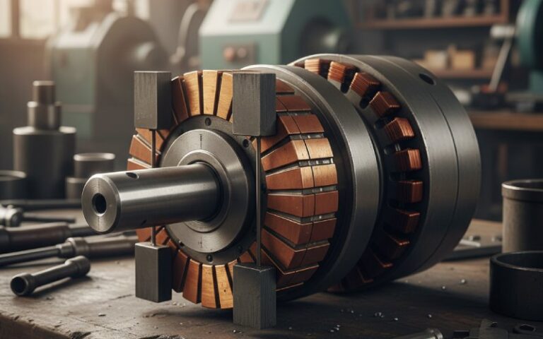
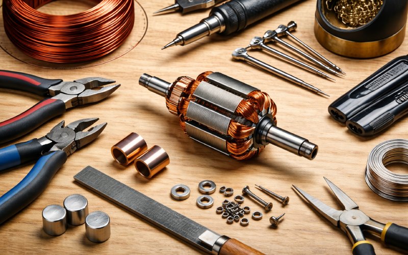
6. Armature core, winding, and joints
You already have slot fill, turns, and conductor size figured out.
Here the focus is the interface to the commutator.
6.1 Core and slots
- Stack laminations and secure (weld, bond, etc.)
- Deburr slot edges and respect slot insulation
- Do not leave burrs where they can cut enamel
6.2 Winding and lead routing
- Wind coils to your pattern and keep lead length consistent
- Route coil ends toward the risers in a way that keeps space for undercutting
- Avoid crossings so dense that varnish cannot penetrate
6.3 Joints to commutator risers
This is where many motors technically “work”, but age badly.
Things to watch:
- Soft solder alone on high-speed armatures runs into issues with heat, vibration, and centrifugal force
- Poor joints create resistance that changes with temperature
Better options in most industrial cases:
- Resistance welding, brazing, or high-silver solder
- Fixtures that hold wires and risers in a repeatable geometry
- Clear visual criteria:
- no visible voids
- no loose globules or icicles of metal
- no damage to insulation at the joint area
For critical designs, sample joints can be pull-tested or checked after thermal cycles.
7. Impregnation and curing
Short section, still important:
- Impregnate the armature with varnish or resin matched to your insulation class
- Use controlled cure profiles so the commutator does not see strong thermal gradients
- Avoid curing in a way that locks in stress between shaft, commutator, and core
Once cured, the armature is ready for finishing work on the copper surface.
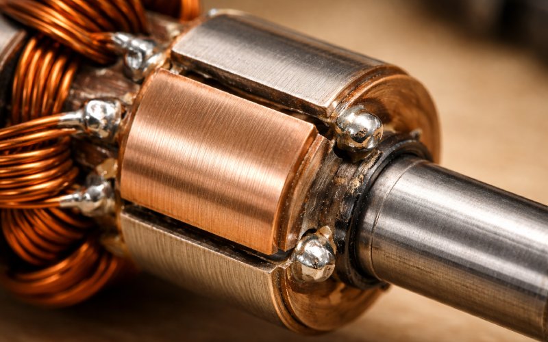
8. Final machining, undercutting and cleaning
This is the part everyone recognises visually. A lot of field problems start here.
8.1 Turning to final size
- Machine the commutator to final diameter on a stable setup
- Hit the runout numbers you decided earlier
- Avoid aggressive cuts that leave chatter marks or work-harden bar edges
8.2 Undercutting the insulation
Purpose is simple: brushes should run on copper, not on high insulation ridges.
Common practice:
- Saw-cut the mica or other insulation between bars
- Target depth from the finished copper surface:
- about 1–1.5× slot width
- values around 1/16″ for many medium-sized machines
Try to keep the cut centered between bars. Off-centre undercutting leaves uneven mica that is harder to clean.
8.3 Removing fins and chamfering
After undercutting:
- Remove mica fins on slot walls with files or scrapers
- Clean out all debris from slots (vacuum or dry air)
- Apply a small chamfer on bar edges, around the 1/64″ range, to remove sharp copper lips
Those small steps are cheap. Skipping them is expensive later.
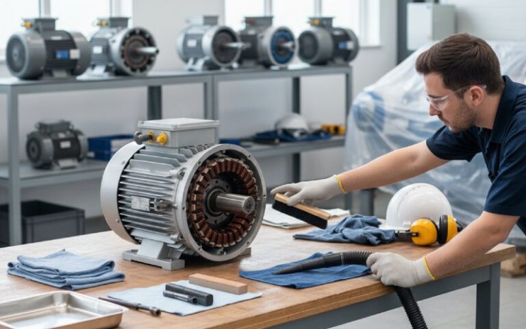
8.4 Surface conditioning
- With the armature turning at controlled speed, use suitable commutator stones
- Aim for a uniform, fine texture
- Avoid emery cloth; conductive abrasive particles do not help you here
Now the commutator is geometrically ready for brush work.
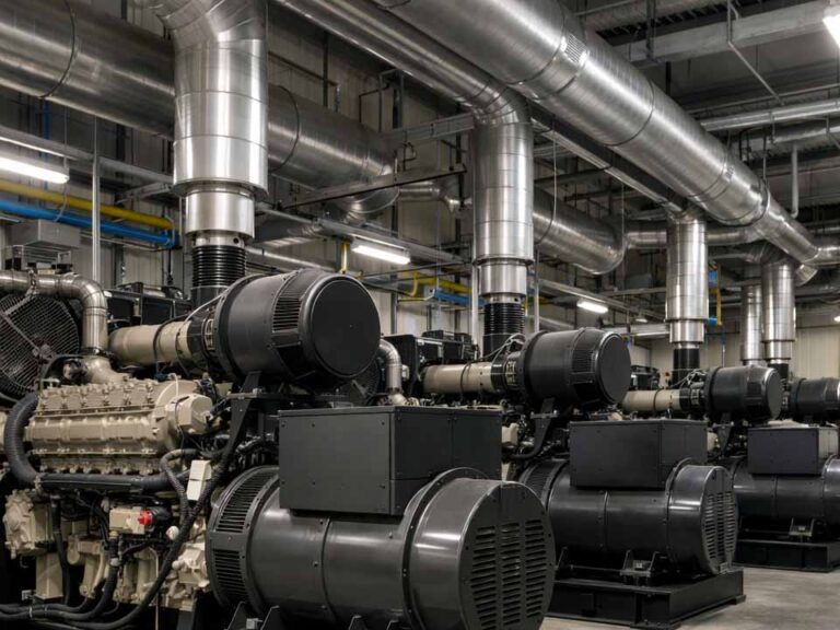
9. Stator assembly and mechanical stack
This guide is not mainly about stators, but you still need the basics right.
- Mount magnets or field poles in the frame
- Fit bearings to shaft journals with defined fits
- Assemble rotor, stator, and end shields
- Rotate by hand, listen and feel for rubbing, tight spots, or rough bearings
Misalignment here often shows later as uneven brush wear and a “mysterious” commutation problem.
10. Brush gear and neutral setting
This part looks trivial on drawings and then eats days in real life.
10.1 Brush holders and spring force
Decide and document:
- Brush cross-section and length
- Number of brushes per track
- Acceptable overhang beyond the last bar
- Spring force range
Check in production:
- Brush slides freely in the holder with sensible clearance
- Spring force hits the design window, not just “feels right”
- Holder faces are square to the commutator surface
10.2 Seating
Two typical worlds:
- Production
- Pre-shaped brushes or controlled run-in on a seating stand
- Goal: high contact area in a short, predictable time
- Maintenance / repair
- Brush stones or fine abrasive strips may be used by hand to match the radius
On paper, it helps to label which method is for factory use and which is for field work, so people do not mix them up.
10.3 Practical neutral setting
Instead of “turn the brush ring until sparks look small”, use a repeatable method. One simple example:
- Run the motor close to rated speed and a defined load.
- Measure voltage between a brush and commutator bars around that brush.
- Rotate the brush rig until the measured commutation voltage in that zone is as close to zero as your method allows.
- Mark that position as the neutral for that load point and record the angular offset.
Other methods exist (DC or AC kick tests, dedicated instruments). The important part is:
- Give the method a name
- Write down the steps
- Put clear neutral marks on the hardware
11. Electrical, thermal and commutation tests
After assembly, you still need to see whether the motor behaves like the design you thought you built.
Typical checks:
- No-load test
- Apply rated voltage
- Measure speed and current
- Compare with your acceptance window
- Load test
- Preferably on a dynamometer
- Check torque, speed, efficiency, winding temperature and commutator region temperature
- Commutation observation
- Inspect the brush zone under expected operating conditions
- Look for:
- Normal: thin, even film; light, intermittent sparking
- Concerning:
- Regular bar patterns with dark, etched edges
- Continuous strong sparking across the brush width
- Helical grooves forming on the copper
Define allowed spark length and film variation in advance, so quality checks are not purely a matter of opinion.
12. Assembly-related failure modes and controls
These issues may not show at first power-up. They appear later as warranty events.
12.1 Press-fit damage
Symptoms:
- Runout out of spec, sometimes drifting over time
- Localised commutator wear bands
- Cracks or stains near the hub when the motor is stripped
Controls:
- Proper fixturing and support during pressing
- Defined interference range
- Limits on acceptable runout shift between bare commutator and pressed assembly
In our own process, press-fitting is not just “push it on and forget it”.
The hub is supported during pressing, and concentricity is checked again after curing and machining, not only on bare parts.
If press-fit damage has been a recurrent failure mode in your motors, it helps to mention shaft size and target speed when you talk to a supplier.
That allows us, or any supplier, to suggest hub designs and tolerances that are safer for your application.
12.2 Mica fins and dirty slots
If mica fins stay on slot walls:
- Brushes catch and bounce
- Arc marks appear at bar edges
- The film becomes unstable and patchy
Controls:
- Always clean fins after undercutting
- Randomly inspect a sample of armatures under magnification
- Keep slots free of copper dust or abrasive particles
In our own process, undercutting is always followed by deburring and slot cleaning.
That extra pass costs a little time at the factory but is still cheaper than dealing with brush bounce and bar burning in the field.
If you are troubleshooting a motor that keeps burning brushes or bars, pictures of the commutator surface and slot edges often reveal whether fins and debris are part of the story.
You can send clear photos to a supplier or an in-house specialist before you commit to a full redesign.
12.3 Weak or inconsistent joints at risers
Symptoms:
- Localised heating around certain commutator regions
- Intermittent or open bars after thermal cycling
Controls:
- Repeatable joining process (welding or soldering)
- Visual acceptance criteria that are actually enforced on the line
- Sample pull-tests and resistance re-check after thermal cycling
12.4 Brush gear alignment
Misaligned holders and uneven springs cause:
- Unequal current sharing between brushes
- Faster wear on one side of the commutator
- Noise and visible sparking even at moderate loads
Controls:
- Simple gauges for squareness and radial position of holders
- Routine checks of spring forces
- Periodic inspection of brush contact patterns after run-in
13. Small practical habits
Some habits are not glamorous, but they work:
- Protect windings from chips during machining
- Once neutral is set, mark it clearly with punch marks or engraved lines
- Track commutator diameter over service life, not just once
- Avoid mixing brush grades on the same track unless you have test data
These small things stop a lot of “mystery failures” from appearing.
If you want help applying this
This guide is intentionally generic. Real motors never are.
If you are working on a new platform, or fixing a recurring commutation problem, usually the following information is enough to start a useful discussion:
- Voltage and power rating
- Base speed and duty cycle
- Approximate frame size and environment
- Brush grade you use or plan to use (if already selected)
With that, an engineer can look at your numbers and tell you whether your current commutator targets are reasonable or should be tightened or relaxed.
If you want to turn this into a concrete commutator spec for RFQs, collect:
- Voltage and power
- Base speed and duty cycle
- Shaft diameter and desired commutator OD
- Any existing commutator drawing or photo (if you already have a motor)
Then [contact our engineering team].
From that, it is straightforward to create a draft specification you can use to compare suppliers or improve an existing design.
FAQ – Practical questions
Q1. Do I always need to undercut the mica?
If you use carbon-based brushes and the motor is more than a toy, the usual answer is “yes”.
When mica is flush with or above the copper:
1. Brushes can ride on insulation instead of copper
2. Sparking and edge erosion become hard to control
3. Brush life and commutator life both drop
So in most industrial cases, undercutting and keeping it maintained is standard practice.
Q2. How do I choose an initial brush current density?
Many industrial designs start around 8–12 A/cm² of true brush contact area, assuming common grades.
A practical approach:
1. Pick a value in that band based on the brush supplier’s tables
2. Validate with tests for temperature, wear, and film stability
3. Adjust as needed but stay inside the brush maker’s recommended range
Q3. When should I re-undercut in service?
Not by calendar time, but by condition:
1. When copper wear brings the mica close to or above the brush track
2. When sparking remains hard to control even after neutral and brush checks
At that point, re-undercut the mica, remove fins, re-chamfer edges, and repeat your commutation checks.
Q4. Is stoning acceptable on production machines?
Used correctly, yes:
1. Use proper commutator stones
2. Keep speed and pressure under control
3. Avoid abrasive materials that leave conductive grit in the copper
Stones are for improving the surface, not for correcting big mechanical errors or large runout.
Q5. Is soft solder enough for commutator joints?
For very small, low-speed devices, sometimes yes.
For higher speeds, higher temperatures, or heavier duty:
1. Soft solder alone usually ages poorly
2. It is safer to use resistance welding, brazing, or high-silver solder with suitable joint design
Mechanical loading and thermal cycles are the real constraints here.
Q6. Why do some bars get darker than others during operation?
Regular light and dark bar patterns often mean the current or voltage distribution during commutation is uneven.
If trailing edges of some bars show etched or burned regions:
1. Check neutral position
2. Check actual load conditions
3. Check brush grade and spring settings
Patterns that keep worsening over time are usually a warning, not just cosmetic.
Q7. How tight does commutator runout really need to be?
Many industrial machines aim for:
1. Total runout around 0.002″ (0.05 mm) or better
2. Very small bar-to-bar variation
For slower, lightly loaded motors you may tolerate more.
For high-speed, heavy-duty machines, keeping runout tight is usually cheaper than dealing with brush problems later.