BLDC Motor Commutation: Choosing How Your Torque Looks And Behaves
BLDC motor commutation is where you quietly decide how your product will sound, how smooth it will feel, how long the silicon will survive, and how awkward debugging will be five months before launch. Everything else in the drive more or less rearranges itself around that decision.
Table of Contents
What “commutation” really sets for you
Official documentation explains that commutation is just switching the stator phases in sync with the rotor. Useful, but slightly too polite.
In practice, the commutation scheme fixes the character of the whole drive: how much torque ripple you accept, how much math your MCU needs to do, how the DC-link capacitor is stressed, what kind of current sensors you pay for, and how painful low-speed operation becomes. Trapezoidal, sinusoidal, and field-oriented schemes are not just “three methods”; they carve out different operating envelopes.
If you start from the motor, its back-EMF shape, magnet layout and slot/pole choice already nudge you toward a commutation style. A motor wound for relatively flat back-EMF tolerates six-step block commutation nicely; a machine with clean sinusoidal back-EMF is quietly asking for sinusoidal or FOC control, even though you can force it to run with block drive.
Block / six-step commutation: when you just want motion
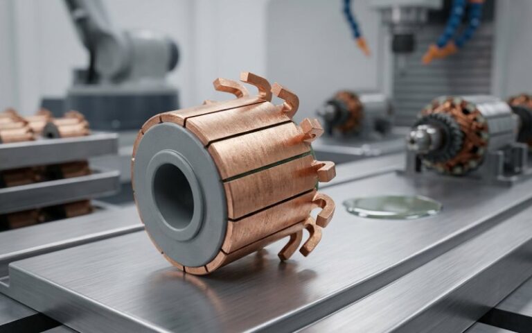
Block commutation, six-step, trapezoidal, 120-degree conduction; different names, same idea. At every 60 electrical degrees you switch which two of the three phases conduct, leaving the third phase floating. A Hall table or back-EMF zero crossing detector picks the state.
This method keeps the control electronics simple: a three-phase bridge, some gate drivers, a few comparators or Hall inputs, and modest firmware. That simplicity explains why power tools, fans, and pumps still ship massive volumes of block-commutated BLDC drives.
The cost is well-known and sometimes underestimated. Torque shows a distinct six-pulse structure per electrical revolution, feeding straight into vibration, acoustic noise, and bearing stress. Research papers treating “commutation torque ripple suppression” as a dedicated topic exist for a reason.
If you stay with block commutation, the interesting engineering work shifts from “which scheme” to “how clean can we make this scheme behave.” That usually means: tightening Hall sensor placement, tuning commutation advance under load, shaping current rise with appropriate gate resistance and dead time, and stabilizing the DC-link so that voltage sag across a step does not amplify torque ripple. Qorvo’s application material and similar notes keep returning to the same idea: correct switch timing dominates everything.
Low-speed operation is the usual sore spot. Sensorless zero-crossing algorithms need enough back-EMF to work, so you fake it with forced commutation, align pulses, or hybrid sensored/sensorless schemes. If your product spends real time below a few hundred electrical rpm, treating that region as a separate operating mode tends to pay off.
Sinusoidal commutation and FOC: torque as a continuous quantity
Sinusoidal commutation simply tries to match the phase currents to sinusoidal back-EMF, keeping torque nearly constant over an electrical revolution. That alone already cuts torque ripple and acoustic artifacts, particularly at low speed where block commutation is at its worst.
Field-oriented control takes the same idea and moves it into a rotating reference frame. Instead of juggling three currents with offsets in space and time, you regulate two orthogonal components aligned and orthogonal to the rotor field. The method resembles sinusoidal commutation on the outside, but now you can directly command torque and flux channels, add current limits, and enforce dynamics in a much more structured way.
The price tag is not mainly the CPU cycles any more; modern MCUs handle Clarke/Park transforms routinely. The more annoying cost is infrastructure: accurate, fast current sensing on at least two phases, reasonably precise rotor position (Hall interpolation, encoder, or advanced observer), careful latency budgeting between sampling and PWM updates, and firmware discipline.
FOC starts to make sense when at least one of these statements is true. Your application has strict acoustic limits at low speed. Your control loop needs to squeeze efficiency over a wide speed range. The motor is overspecified mechanically but constrained thermally so current control becomes the bottleneck. Or you want the same control stack to support both BLDC and PMSM style machines in a common platform.
Sensored and sensorless commutation: how you know where the rotor is
All commutation schemes collapse if you are wrong about rotor position. The choice is simple to write down: use sensors, or infer position from electrical behavior; the implementation is less friendly.
Hall sensors give three digital signals with 60-degree or 120-degree resolution. They are easy for block commutation, and still useful for FOC as coarse anchors interpolated by observers. The documentation from multiple vendors converges on the same picture: embedded Hall sensors are common, low-cost, and remove most issues with startup and low-speed torque.
Sensorless approaches replace physical sensors with back-EMF detection, model-based observers, or high-frequency injection. Back-EMF zero-crossing methods remain the most common for cost-sensitive drives, but they require a minimum speed and clean phase voltage sensing. More advanced observers combine motor models with current and voltage measurements to estimate position and speed; modern survey papers read more like control theory textbooks than motor notes.
A practical rule: if the application must deliver deterministic torque from standstill against unknown load (robot joints, gimbals, servo axes), some form of sensored or hybrid scheme usually simplifies life. If it is a fan, pump, or blower that starts against relatively predictable load, sensorless with a carefully designed startup routine hits a better cost point.
How commutation shows up as torque ripple, EMI and noise
Users do not see your block diagram; they see torque ripple, acoustic noise, and sometimes EMI test failures. All of these are tightly linked to the commutation method and how cleanly it is implemented.
Torque ripple at commutation instants is a frequent topic in academic and industrial work. It shows up when inductance, current, and back-EMF do not transition in step across a switching event. For BLDC drives on tight DC-link capacitance, the interaction between switching and supply ripple becomes important enough that people propose explicit DC-link boosting strategies during non-commutation intervals just to keep ripple under control.
Wide reviews of BLDC reliability issues list torque ripple, EMI, acoustic noise, and commutation faults together. That grouping is not accidental; hard switching of rectangular currents and phase voltages naturally excites mechanical resonances and radiates. Sinusoidal and FOC schemes replace those rectangular edges with smoother waveforms, which tends to reduce both acoustic content and EMI, although gate-drive design and layout still matter.
When you are deciding on a commutation scheme, it is often helpful to start from the worst system constraint. If conducted EMI is already close to regulatory margins, or the mechanical assembly amplifies a certain harmonic, then that will strongly bias the choice toward smoother current profiles, even if the MCU looks slightly over-specified on paper.
Comparing the main commutation styles at a glance
The table below compresses the three dominant schemes into a format that matches real design conversations more than marketing slides. It is intentionally opinionated.
| Commutation style | Typical control signals | Rotor position requirement | Main benefits in practice | Main penalties in practice | Where it tends to win |
|---|---|---|---|---|---|
| Block / six-step (trapezoidal) | Six discrete phase states with 120-degree conduction, simple PWM on upper or lower switches | Hall sensors or simple back-EMF detection with zero-crossing logic | Simple gate drive, modest MCU, easy to understand on a scope, tolerant of rough motors | Pronounced torque ripple, stronger acoustic content, awkward very-low-speed behavior, EMI shaped by hard edges | Fans, pumps, blowers, power tools, small compressors, low-cost motion where “it spins reliably” is the main requirement |
| Sinusoidal (three-phase sines) | Analog or PWM-synthesized sinusoidal currents in all phases | Hall interpolation, encoder, or accurate sensorless observer | Much smoother torque, better low-speed control, lower acoustic and mechanical stress, easier EMI control than block | More complex current control, needs better current sensing and position estimation, higher firmware complexity | Appliances that must sound restrained, mid-range robotics, mid-power pumps, drives where efficiency and comfort both matter |
| FOC / vector control | d-q current loops with decoupling, field-aligned torque control, often with space-vector PWM | High-quality position feedback (encoder, resolvers, or sensorless estimators) and tight control timing | Direct torque control, robust current limiting, good dynamic response, one control platform for many motor variants | Demands disciplined firmware structure, precise sensing chain, trickier failure handling, more tuning parameters | Servo drives, cobots, gimbals, EV auxiliaries, traction systems, anything that lives close to performance envelopes |
The exact borders are fuzzy. Many successful products sit in the gaps: block commutation with clever current shaping, sinusoidal drives with minimal DSP work, FOC running on cheap MCUs with only Hall feedback and interpolation. Real products do not follow textbook partitions.
Matching commutation to application constraints
Rather than asking “which commutation is best,” it is often more productive to ask a series of slightly uncomfortable questions. How much torque ripple is acceptable at the worst-case operating point. How noisy is the mechanical path from the motor to the user’s hand or ear. How much current measurement can the BOM carry without starting arguments.
For a simple HVAC fan running mostly near one operating point, block commutation might be entirely sufficient, especially if the mechanical structure already filters higher harmonics. A washing machine drive with strict acoustic limits and variable speed across a wash cycle often ends up with sinusoidal or FOC control, simply because block commutation would force compromises everywhere else. Automotive pumps, compressors, and auxiliaries frequently use sensored or hybrid approaches: they must start against uncertain loads, meet EMC standards, and integrate into a crowded electrical environment.
The idea is to let system-level constraints drive the commutation style, then design the rest of the electronics around that choice, not the other way around.
Debugging commutation problems without getting lost
When a BLDC system “runs roughly” or vibrates, it is tempting to suspect exotic firmware bugs. In many real cases, the root cause is simpler: incorrect phase order between motor and bridge, wrong commutation table, misaligned Hall sensors, or commutation timing that never got revisited after a motor change. Industrial troubleshooting guides repeatedly highlight phase sequence errors and incorrect timing as first checks for rough operation.
A useful approach is to treat commutation as a timing diagram problem before treating it as a software problem. You verify that phase voltages, back-EMF, and position signals line up in the expected electrical angle. You confirm that the DC-link voltage and current sensors do not saturate during switching events. You check that dead time does not silently chew into the effective voltage at certain load conditions. Only once those are correct does it make sense to tweak observers, speed loops, and torque commands.
For sensorless drives, startup is where most latent issues show themselves. If the motor stalls or chatters during open-loop alignment, that is usually a sign of mismatched electrical parameters, not yet of deep control errors. Getting a robust alignment and ramp strategy in place often solves “mystery” zero-speed faults.
A practical migration path: from block to “almost FOC”
Many teams start with six-step commutation, get a prototype working, and then hit acoustic or control limits. Throwing all of that away and jumping directly to full FOC feels risky, so the system stays noisy for another product cycle. There is a calmer route.
One common path is to keep the existing bridge hardware and Hall sensors, but start adding sinusoidal modulation on top of the commutation pattern, gradually shaping currents closer to what the back-EMF really wants. That reduces ripple without forcing an immediate architectural shift.
The next step is to introduce current regulation in the stationary frame, then move into a rotating reference frame once you are happy with measurement quality and timing. By the time you implement full d-q control, much of the low-level infrastructure is already proven. The transition becomes a series of small changes rather than a single rewrite.
Closing thoughts
BLDC motor commutation is not just a configuration option in a library; it is a structural choice about how your motor, mechanics, and electronics interact over the entire product life. Block, sinusoidal, and FOC schemes all have strong use cases, and modern research around torque ripple reduction, EMI handling, and sensorless estimation simply sharpens those tools rather than replacing them.
If you treat commutation as a design decision made once at the start and then regularly revisited as the system matures, you avoid the usual trap where the scheme is chosen just to make the first rotor spin. The motor will turn either way; the question is whether it does so in a way that matches the system constraints you actually face.