Armature vs Commutator: Don’t Mix Up the Muscle and the Switch
When people first open up a DC motor or generator, two parts usually cause the most confusion: the armature and the commutator. They sit close together, rotate together, and are wired together — so it’s tempting to think they’re basically the same thing.
They’re not.
If the armature is the muscle of the machine, the commutator is the switching brain that keeps that muscle working in the right direction. Mixing them up makes it harder to troubleshoot, design, or even talk clearly about DC machines.
In this guide, we’ll go beyond basic textbook one-liners and build a deep, intuitive understanding of what each part does, how they interact, and how to tell them apart instantly — both in theory and in hardware.
- Already know a bit and just want the short version?
- Armature = part with the windings/coils that convert energy (electrical ↔ mechanical) in the magnetic field.
- Commutator = mechanical switch on the shaft that regularly reverses or routes current so torque or output current stays in one direction.
- In DC motors: armature creates torque; commutator keeps that torque rotating in a constant direction.
- In DC generators: armature generates AC in its windings; commutator “rectifies” it to DC for the outside world.
Table of Contents
Big Picture: Where Armature and Commutator Live in a DC Machine
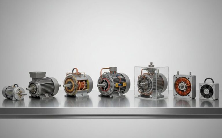
Let’s zoom out. A DC machine (motor or generator) has two main magnetic players:
- A stator (field system) that provides a magnetic field.
- A rotor, usually called the armature in DC machines, that turns inside that field and carries armature windings.
The armature is where energy conversion actually happens:
- In a motor, electrical energy in the armature winding becomes mechanical rotation.
- In a generator, mechanical rotation in the armature becomes electrical energy.
But there’s a problem: as the armature rotates through the magnetic field, the induced or required current in its coils naturally changes direction every half turn. Left untreated, that would give us:
- Reversing torque in a motor → it would jerk back and forth instead of spinning smoothly.
- Alternating voltage in a DC generator’s armature → but we want DC at the terminals.
Enter the commutator: a segmented copper cylinder whose whole job is to flip or route the connections between the rotating armature coils and the external circuit at just the right time, keeping torque or output current unidirectional.
- Think of the machine like this:
- Field = the “magnetic playground” (stator).
- Armature = the “kid on the swing” converting energy inside that playground.
- Commutator + brushes = the “smart timing system” that pushes or collects energy at exactly the right moments so the swing keeps going in one direction.
What Is an Armature, Really? (Not Just “Some Coils”)
The armature is more than just copper wire. It’s a carefully engineered package designed to carry current in a magnetic field efficiently and reliably.
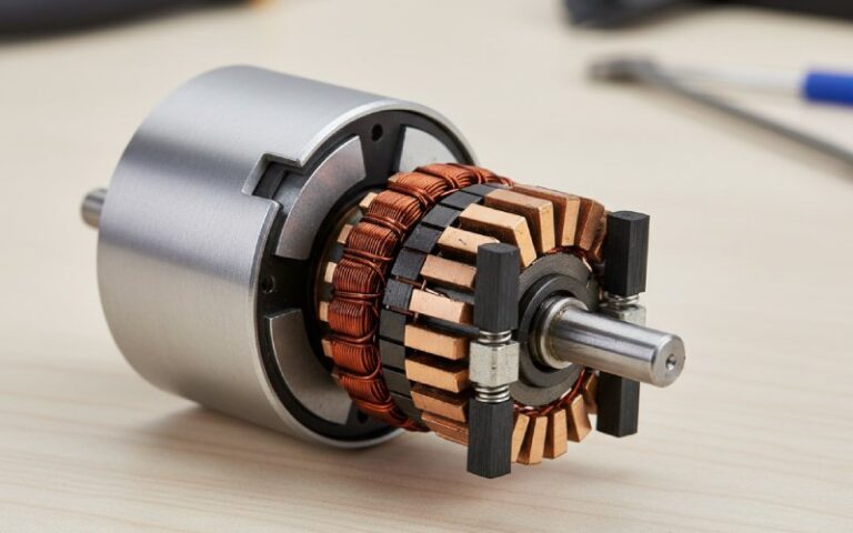
In a DC machine, the armature usually consists of:
- A laminated iron core, made of thin silicon-steel sheets to reduce eddy current losses.
- Slots on the surface to hold the armature windings (coils).
- The shaft, which transmits mechanical power and supports the rotor.
- At one end of the shaft, the commutator is mounted — but it is considered a separate component.
Functionally, the armature does two big jobs:
- Carry current in the magnetic field
- In a motor, current in the armature windings interacts with the field to produce torque (via the Lorentz force).
- In a generator, motion through the magnetic field induces EMF in the armature windings (Faraday’s law).
- Provide the “energy conversion zone”
- All the serious electrical ↔ mechanical energy conversion is happening in or near the armature conductors.
- That’s why armatures are designed with special winding patterns (lap, wave winding) and laminated cores to reduce losses and control performance.
In short:
The armature is where the physics happens — where magnetic fields and currents meet to create torque or voltage.
- Armature at a Glance (DC Machines)
- Location: Rotating part (rotor) in most DC machines.
- Main material: Laminated iron core + copper windings.
- Key role in motors: Converts electrical power to mechanical torque.
- Key role in generators: Induces EMF and delivers electrical power (before commutation).
- Type of current in windings: Fundamentally AC in nature, even in “DC” machines, because the direction reverses with rotation.
- Design tricks: Laminations to cut eddy currents, different winding schemes (lap/wave) to optimize for high current or high voltage.
What Is a Commutator, Exactly? (And Why Does Everyone Draw It Wrong?)
If the armature is the muscle, the commutator is the mechanical switching device that keeps that muscle pulling in the same useful direction.
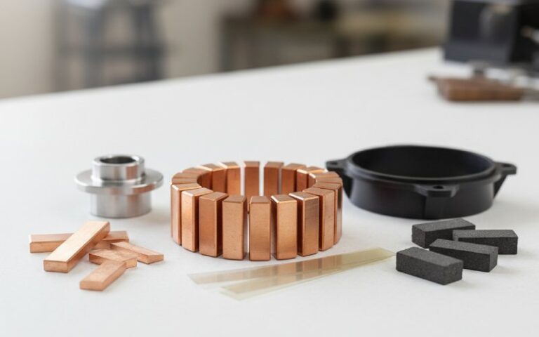
Physically, a commutator is:
- A cylindrical drum mounted on the shaft.
- Built from many copper segments, arranged around the shaft like slices of an orange.
- Each segment is insulated from its neighbors with materials like mica (thin, high-temperature insulation).
- Each segment is connected to the ends of armature coils.
Stationary brushes (usually carbon/graphite blocks) press against the commutator surface and connect it to the external circuit or DC supply. As the rotor turns, the combination of rotating segments and stationary brushes changes which coil is connected to which polarity — that’s commutation.
What the Commutator Actually Does
- In DC motors:
- It reverses the current direction in each armature coil every half turn.
- That reversal keeps the torque direction constant, so the motor keeps spinning rather than rocking back and forth.
- In DC generators:
- The armature windings naturally generate AC as they cut the magnetic field.
- The commutator acts as a mechanical rectifier, flipping the connections so the output at the brushes is unidirectional DC.
- In both:
- It forms the interface between the rotating armature windings and the stationary external circuit.
So while the armature is where energy conversion occurs, the commutator is what makes that conversion usable as DC or usable torque.
- Commutator at a Glance
- Location: On the shaft, adjacent to the armature core, rotating with it.
- Main material: Segmented copper, insulated with mica or similar.
- Primary function in motors: Reverse current in armature windings at the correct moment to maintain continuous torque.
- Primary function in generators: Convert internally generated AC to DC at the terminals (mechanical rectifier).
- Works with: Stationary brushes that collect or supply current.
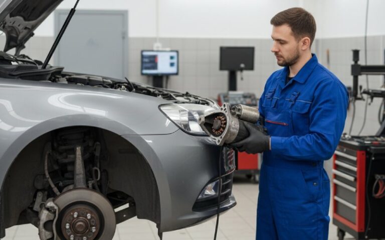
- Failure symptoms: Heavy sparking, pitted or burned segments, uneven wear, excessive brush heating.
Armature vs Commutator: Side-by-Side Comparison
Now let’s put all of that into a single, high-contrast comparison you can refer back to.
Quick Comparison Table
| Aspect | Armature | Commutator |
| What it is | The winding + core where energy conversion happens | A rotary switch that manages current direction/collection |
| Location | Rotor (in DC machines), with slots holding windings | Mounted on the shaft beside the armature, in contact with brushes |
| Made of | Laminated steel core + copper windings | Copper segments insulated by mica or similar material |
| Main job in a motor | Carry current in field → produce torque | Reverse current in coils to keep torque direction constant |
| Main job in a generator | Cut magnetic field → generate EMF (usually AC in the windings) | Rectify this to DC at the brushes/output terminals |
| Type of current inside | AC in nature (direction reverses as rotor turns) | Sees DC at the brushes, but segments sequentially connect different coils |
| Energy role | Site of actual energy conversion (electrical ↔ mechanical) | Routing and shaping current so energy is usable as DC |
| Connected to | Coils connected to commutator segments | Segments connected to armature coils; brushes contact the commutator |
| Typical failure clues | Overheating, burned windings, inter-turn shorts, reduced torque/EMF | Sparking, segment burning, uneven wear, noisy operation |
| If removed | No torque or generated voltage → the machine is dead | Motor still produces forces, but torque reverses and machine is useless as DC |
Notice how their roles do not overlap:
- The armature handles physics and power.
- The commutator handles timing and direction of current.
If you’re troubleshooting or designing, mixing these roles up makes it much harder to reason about what’s going wrong.
Bringing It All Together
If you remember only one thing, make it this:
The armature is where you create torque or EMF; the commutator is what makes that torque or EMF useful as DC and continuous rotation.
Once you see them as a team — muscle + switching brain — everything else about DC machines falls into place: commutation problems, sparking, torque ripple, and even why modern brushless motors got rid of the mechanical commutator and replaced it with electronics.